TMS3705
11-07-22-003 – SCBS881B –JANUARY 2010–REVISED APRIL 2010
www.ti.com
Transponder Resonance-Frequency Measurement
During the pre-bit reception phase, the bits the transponder transmits show the low-bit frequency, which is the
resonance frequency of the transponder. The time periods of the pre-bits are evaluated by the demodulator
counter. Based on the counter states, an algorithm is implemented that guarantees a correct measurement of the
transponder’s resonance frequency:
1. A time period of the low-bit frequency has a counter state between 112 and 125.
2. The measurement of the low-bit frequency (the average of eight subsequent counter states) is accepted
during the write mode, when the eight time periods have counter states in the defined range. The
measurement during write mode is started with the falling edge at TXCT using the fixed delay time at which
end the full bridge is switched on again.
3. The counter state of the measured low-bit frequency results in the average counter state of an accepted
measurement and can be used to update the register of the programmable frequency divider.
4. The measurement of the low-bit frequency (the average of eight subsequent counter states) is accepted
during the read mode, when the eight time periods have counter states in the defined range. The start of the
measurement during read mode is delayed in order to use a stable input signal for the measurement.
5. The threshold to distinguish between high-bit and low-bit frequency is calculated to be by a value of 5 or 7
(see hysteresis in threshold) higher than the counter state of the measured low-bit frequency.
SCI Encoder
An SCI encoder performs the data transmission to the microcontroller. As the transmission rate of the
transponder is lower than the SCI transmission rate, the serial bit flow received from the transponder is buffered
after demodulation and before SCI encoding.
The SCI encoder uses an 8-bit shift register to send the received data byte-wise (least significant bit first) to the
microcontroller with a transmission rate of 15.625 kbaud (±1.5 %), one start bit (high) and one stop bit (low), but
no parity bit (asynchronous mode indicated by the SYNC bit of the mode control register permanently low). The
data bits at the SCIO output are inverted with respect to the corresponding bits sent by the transponder.
The transmission starts after the reception of the start bit. The start byte detection is initialized with the first rising
edge. Typical values for the start byte are 81_H or 01_H (at SCIO). The start byte is the first byte to be sent to
the microcontroller. The transmission stops and the base station returns to idle state when TXCT becomes low or
20 ms after the beginning of the read phase. TXCT remains low for at least 128 µs to stop the read phase and
less than 900 µs to avoid starting the next transmission cycle.
The SCI encoder also sends the diagnostic byte 2 ms after beginning of the charge phase. In case of a normal
operation of the antenna, the diagnostic byte AF_H is sent. If no antenna oscillation can be measured or if at
least one of the full-bridge drivers is switched off due to a detected short-circuit, the diagnostic byte FF_H is sent
to indicate the failure mode.
The SCI encoder can be switched into a synchronous data transmission mode by setting the mode control
register bit SYNC to high. In this mode, the output SCIO indicates by a high state that a new byte is ready to be
transmitted. The microcontroller can receive the eight bits at SCIO when sending the eight clock signals (falling
edge means active) for the synchronous data transmission via pin TXCT to the SCI encoder.
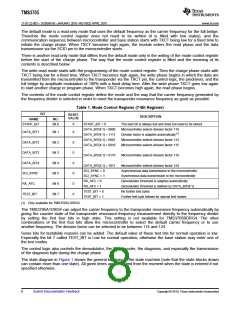
Control Logic
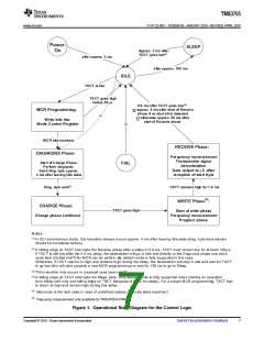
The control logic is the core of the TMS3705 circuit. It contains a sequencer or a state machine that controls the
global operations of the base station (see Figure 1). This block has a default mode configuration but can also be
controlled by the microcontroller via the TXCT serial input pin to change the configuration and to control the
programmable frequency divider. For that purpose a mode control register is implemented in this module that can
be written by the microcontroller.
6
Submit Documentation Feedback
Copyright © 2010, Texas Instruments Incorporated

 TI [ TEXAS INSTRUMENTS ]