TMS320DM6437
Digital Media Processor
www.ti.com
SPRS345B–NOVEMBER 2006–REVISED MARCH 2007
6.13.3 HPI Electrical Data/Timing
Table 6-56. Timing Requirements for Host-Port Interface Cycles(1)(2) (see Figure 6-32 through Figure 6-35)
-400
-500
-600
NO.
UNIT
MIN
MAX
1
2
tsu(SELV-HSTBL)
th(HSTBL-SELV)
tw(HSTBL)
Setup time, select signals(3) valid before HSTROBE low
Hold time, select signals(3) valid after HSTROBE low
Pulse duration, HSTROBE active low
5
2
ns
ns
ns
ns
ns
ns
ns
ns
3
15
2M
5
4
tw(HSTBH)
Pulse duration, HSTROBE inactive high between consecutive accesses
Setup time, select signals(3) valid before HAS low
Hold time, select signals(3) valid after HAS low
9
tsu(SELV-HASL)
th(HASL-SELV)
tsu(HDV-HSTBH)
th(HSTBH-HDV)
10
11
12
2
Setup time, host data valid before HSTROBE high
Hold time, host data valid after HSTROBE high
5
0
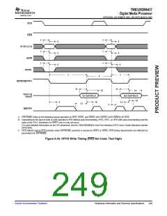
Hold time, HSTROBE low after HRDY low. HSTROBE should not be
inactivated until HRDY is active (low); otherwise, HPI writes will not
complete properly.
13
th(HRDYL-HSTBL)
0
ns
16
17
tsu(HASL-HSTBL)
th(HSTBL-HASL)
Setup time, HAS low before HSTROBE low
Hold time, HAS low after HSTROBE low
2
2
ns
ns
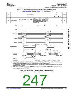
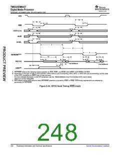
(1) HSTROBE refers to the following logical operation on HCS, HDS1, and HDS2: [NOT(HDS1 XOR HDS2)] OR HCS.
(2) M = SYSCLK3 period = (CPU clock frequency)/6 in ns. For example, when running parts at 600 MHz, use M = 10 ns.
(3) Select signals include: HCNTL[1:0], HR/W and HHWIL.
Submit Documentation Feedback
Peripheral Information and Electrical Specifications
245

 TI [ TEXAS INSTRUMENTS ]