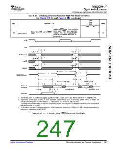
TMS320DM6437
Digital Media Processor
www.ti.com
SPRS345B–NOVEMBER 2006–REVISED MARCH 2007
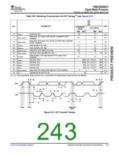
Table 6-54. Switching Characteristics for I2C Timings(1) (see Figure 6-31)
-400
-500
-600
NO.
PARAMETER
UNIT
STANDARD
MODE
FAST MODE
MIN
MAX
MIN
MAX
16
17
tc(SCL)
Cycle time, SCL
10
2.5
µs
µs
Delay time, SCL high to SDA low (for a repeated START
condition)
td(SCLH-SDAL)
4.7
4
0.6
0.6
Delay time, SDA low to SCL low (for a START and a repeated
START condition)
18
td(SDAL-SCLL)
µs
19
20
21
22
tw(SCLL)
Pulse duration, SCL low
4.7
4
1.3
0.6
100
0
µs
µs
ns
µs
tw(SCLH)
Pulse duration, SCL high
td(SDAV-SCLH)
tv(SCLL-SDAV)
Delay time, SDA valid to SCL high
Valid time, SDA valid after SCL low
250
0
0.9
Pulse duration, SDA high between STOP and START
conditions
23
tw(SDAH)
4.7
1.3
µs
(1)
24
25
26
27
28
29
tr(SDA)
tr(SCL)
Rise time, SDA
1000 20 + 0.1Cb
1000 20 + 0.1Cb
300 20 + 0.1Cb
300 20 + 0.1Cb
300
300
300
300
ns
ns
ns
ns
µs
pF
(1)
(1)
(1)
Rise time, SCL
tf(SDA)
Fall time, SDA
tf(SCL)
Fall time, SCL
td(SCLH-SDAH)
Cp
Delay time, SCL high to SDA high (for STOP condition)
Capacitance for each I2C pin
4
0.6
10
10
(1) Cb = total capacitance of one bus line in pF. If mixed with HS-mode devices, faster fall-times are allowed.
26
24
SDA
21
23
19
28
20
25
SCL
16
27
18
17
22
18
Stop
Start
Repeated
Start
Stop
Figure 6-31. I2C Transmit Timings
Submit Documentation Feedback
Peripheral Information and Electrical Specifications
243

 TI [ TEXAS INSTRUMENTS ]