TMS320DM6437
Digital Media Processor
www.ti.com
SPRS345B–NOVEMBER 2006–REVISED MARCH 2007
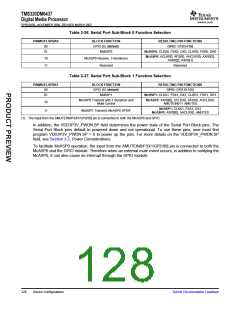
Table 3-36. Serial Port Sub-Block 0 Function Selection
PINMUX1.SPBK0
BLOCK FUNCTION
GPIO (6) (default)
McBSP0
RESULTING PIN FUNCTIONS
00
01
GPIO: GP[104:99]
McBSP0: CLKX0, FSX0, DX0, CLKR0, FSR0, DR0
McASP0: ACLKR0, AFSR0, AHCLKR0, AXR0[3],
10
11
McASP0 Receive, 3 Serializers
Reserved
AXR0[2], AXR0[1]
Reserved
Table 3-37. Serial Port Sub-Block 1 Function Selection
PINMUX1.SPBK1
BLOCK FUNCTION
GPIO (6) (default)
McBSP1
RESULTING PIN FUNCTIONS
00
01
GPIO: GP[110:105]
McBSP1: CLKX1, FSX1, DX1, CLKR1, FSR1, DR1
McASP0 Transmit with 1 Serializer and
Mute Control
McASP0: AXR0[0], ACLKX0, AFSX0, AHCLKX0,
10
11
AMUTEIN0(1), AMUTE0
McBSP1: CLKX1, FSX1, DX1
McASP0: AXR0[0], AHCLKX0, AMUTE0
McBSP1 Transmit, McASP0 SPDIF
(1) The input from the AMUTEIN0/FSX1/GP[109] pin is connected to both the McASP0 and GPIO.
In addition, the VDD3P3V_PWDN.SP field determines the power state of the Serial Port Block pins. The
Serial Port Block pins default to powered down and not operational. To use these pins, user must first
program VDD3P3V_PWDN.SP = 0 to power up the pins. For more details on the VDD3P3V_PWDN.SP
field, see Section 3.2, Power Considerations.
To facilitate McASP0 operation, the input from the AMUTEIN0/FSX1/GP[109] pin is connected to both the
McASP0 and the GPIO module. Therefore when an external mute event occurs, in addition to notifying the
McASP0, it can also cause an interrupt through the GPIO module.
128
Device Configurations
Submit Documentation Feedback

 TI [ TEXAS INSTRUMENTS ]