TMS320C6672
Multicore Fixed and Floating-Point Digital Signal Processor
SPRS708C—February 2012
www.ti.com
Table 3-9
Reset Status Clear Register (RESET_STAT_CLR) Field Descriptions
Description
Bit
Field
GR
31
Global reset clear bit
0 = Writing a 0 has no effect.
1 = Writing a 1 to the GR bit clears the corresponding bit in the RESET_STAT register.
30-2
1
Reserved
LR1
Reserved.
CorePac1 reset clear bit
0 = Writing a 0 has no effect.
1 = Writing a 1 to the LR1 bit clears the corresponding bit in the RESET_STAT register.
0
LR0
CorePac0 reset clear bit
0 = Writing a 0 has no effect.
1 = Writing a 1 to the LR0 bit clears the corresponding bit in the RESET_STAT register.
End of Table 3-9
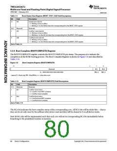
3.3.9 Boot Complete (BOOTCOMPLETE) Register
The BOOTCOMPLETE register controls the BOOTCOMPLETE pin status. The purpose is to indicate the
completion of the ROM booting process. The Boot Complete Register is shown in Figure 3-8 and described in
Table 3-10.
Figure 3-8
Boot Complete Register (BOOTCOMPLETE)
31
2
1
0
Reserved
BC1
BC0
R, + 0000 0000 0000 0000 0000 0000
Legend: R = Read only; RW = Read/Write; -n = value after reset
RW,+0
RW,+0
Table 3-10
Boot Complete Register (BOOTCOMPLETE) Field Descriptions
Bit
31-2
1
Field
Description
Reserved
BC1
Reserved.
CorePac1 boot status
0 = CorePac1 boot NOT complete
1 = CorePac1 boot complete
0
BC0
CorePac0 boot status
0 = CorePac0 boot NOT complete
1 = CorePac0 boot complete
End of Table 3-10
The BCx bit indicates the boot complete status of the corresponding core. All BCx bits will be sticky bits — that is
they can be set only once by the software after device reset and they will be cleared to 0 on all device resets.
Boot ROM code will be implemented such that each core will set its corresponding BCx bit immediately before
branching to the predefined location in memory.
80
Device Configuration
Copyright 2012 Texas Instruments Incorporated

 TI [ TEXAS INSTRUMENTS ]