TLK10002
www.ti.com
SIGNAL
SLLSE75 –MAY 2011
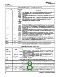
Table 2. Pin Description – Power Pins (continued)
PIN
Type
DESCRIPTION
BGA
A2, A5, A11,
B3, B4, B7,
B11, C1, C6,
C12, D3, D5,
D10, D11, E2,
E4, F1, F5, F8,
VSS
F10, F12, G1, Ground Ground. Common analog and digital ground.
G3, G5, G7,
G11, H2, H4,
H11, J5, J12,
K1, K6, K11, L3,
L4, L7, L11, M2,
M5, M12
FUNCTIONAL DESCRIPTION
The TLK10002 is a versatile high-speed transceiver device that is designed to perform various physical layer
functions. It is equipped with a number of functions and testability features that make it easy to integrate the
device in high-speed communications systems, especially in wireless infrastructure. The details of those features
are discussed in this section.
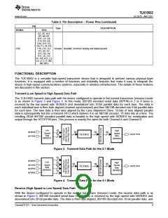
Transmit (Low Speed to High Speed) Data Path
The TLK10002 transmit data path with the device configured to operate in the normal transceiver (mission) mode
is as shown in Figure 3 and Figure 4. In this mode, 8B/10B encoded serial data (IN*P/N) in 2 or 4 lanes is
received by the low speed side SERDES and deserialized into 10-bit parallel data for each lane. The data in
each individual lane is then byte aligned (channel synchronized) and then 8B/10B decoded into 8-bit parallel data
for each lane. The lane data is then lane aligned by the Lane Alignment Slave. 32-bits of lane aligned parallel
data is subsequently fed into a transmit FIFO which delivers it to an 8B/10B encoder, 16 data bits at a time. The
resulting 20-bit 8B/10B encoded parallel data is handed to the high speed side SERDES for serialization and
output through the HSTX*P/N pins. This process is exactly the same for both Channel A and Channel B.
Low
10
High
Speed
Side
IN*0P/N
IN*1P/N
16
16
20
Speed
Side
SERDES
HSTX*P/N
1
0
TX FIFO
SERDES
Figure 3. Transmit Data Path for the 2:1 Mode
10
10
IN*0P/N
Low
High
Speed
Side
32
16
20
Speed
Side
SERDES
IN*1P/N
IN*2P/N
HSTX*P/N
1
0
TX FIFO
SERDES
10
IN*3P/N
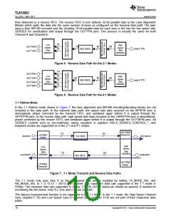
Figure 4. Transmit Data Path for the 4:1 Mode
Receive (High Speed to Low Speed) Data Path
With the device configured to operate in the normal transceiver (mission) mode, the receive data path is as
shown in Figure 6. 8B/10B encoded serial data (HSRX*P/N) is received by the high speed side SERDES and
deserialized into 20-bit parallel data. The data is then byte aligned, 8B/10B decoded into 16-bit parallel data, and
Copyright © 2011, Texas Instruments Incorporated
9

 TI [ TEXAS INSTRUMENTS ]