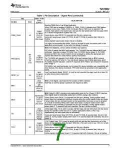
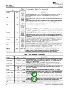
TLK10002
www.ti.com
SLLSE75 –MAY 2011
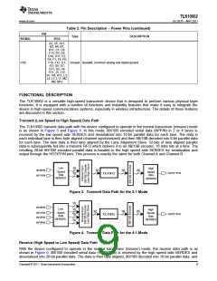
In the 1:1 mode, the data path supports non-8B/10B encoded data, e.g. PRBS.
In this mode, any registers related to lane 1, 2, or 3 are not used or do not apply. In addition, the following
registers do not apply:
•
•
•
•
1.11:8
9.8:4
C, D, 15(except 15.10), 16, 17, 18, 1D
F.14, F.10, F.8, F.3:2
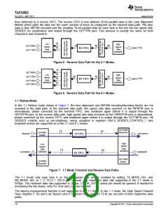
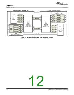
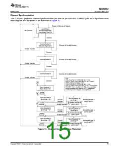
Lane Alignment Scheme
Lower rate multi-lane serial signals per channel must be byte aligned and lane aligned such that high speed
multiplexing (proper reconstruction of higher rate signal) is possible. For that reason, the TLK10002 implements
a special lane alignment scheme on the low speed (LS) side.
During lane alignment, a proprietary pattern (or a custom comma compliant data stream) is sent by the LS
transmitter to the LS receiver on each active lane. This pattern allows the LS receiver to both delineate byte
boundaries within a lower speed lane and align bytes across the lanes (2 or 4) such that the original higher rate
data ordering is restored.
Lane alignment completes successfully when the LS receiver asserts a “Link Status OK” signal monitored by the
LS transmitter on the link partner device such as an FPGA. The TLK10002 sends out the “Link Status OK”
signals through the LS_OK_OUT_A/B output pins, and monitors the “Link Status OK” signals from the link
partner device through the LS_OK_IN_A/B input pins. If the link partner device does not need the TLK10002
Lane Align Master (LAM) to send proprietary lane alignment pattern, LS_OK_IN_A/B can be tied high on the
application board.
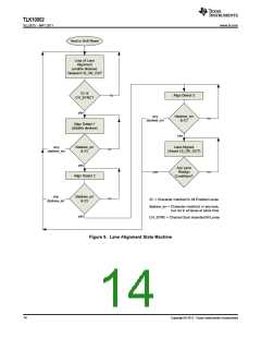
The lane alignment scheme is activated under any of the following conditions:
•
•
•
•
•
•
•
•
•
Device/System power up (after configuration/provisioning)
Loss of channel synchronization assertion on any enabled LS lane
Loss of signal assertion on any enabled LS lane
LS SERDES PLL Lock indication deassertion
After device configuration change
After software determined LS 8B/10B decoder error rate threshold exceeded
After device reset is deasserted
Anytime the LS receiver deasserts “Link Status OK”.
Presence of reoccurring higher level / protocol framing errors
The block diagram of the lane alignment scheme is shown in Figure 8.
Copyright © 2011, Texas Instruments Incorporated
11

 TI [ TEXAS INSTRUMENTS ]