TLK10002
SLLSE75 –MAY 2011
www.ti.com
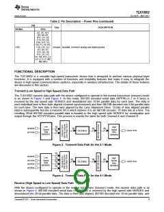
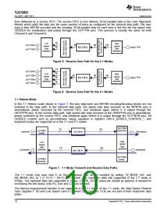
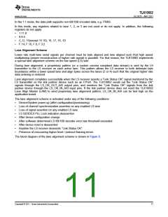
then delivered to a receive FIFO. The receive FIFO in turn delivers 32-bit parallel data to the Lane Alignment
Master which splits the data into the same number of lanes as configured on the transmit data path. The lane
data is then 8B/10B encoded and the resulting 10-bit parallel data for each lane is fed into the low speed side
SERDES for serialization and output through the OUT*P/N pins. This process is exactly the same for both
Channel A and Channel B.
10
10
Low
Speed
Side
High
Speed
Side
16
16
20
OUT*0P/N
OUT*1P/N
*P/N
HSRX
RX FIFO
SERDES
SERDES
Figure 5. Receive Data Path for the 2:1 Modes
10
10
OUT*0P/N
OUT*1P/N
Low
Speed
Side
High
Speed
Side
32
16
20
10
10
*P/N
HSRX
RX FIFO
OUT*2P/N
OUT*3P/N
SERDES
SERDES
Figure 6. Receive Data Path for the 4:1 Modes
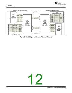
1:1 Retime Mode
In the 1:1 Retime mode shown in Figure 7, the lane alignment and 8B/10B encoding/decoding blocks are not
included in the data path. In the transmit data path, low speed side data received on the IN*0P/N pins is
deserialized, phase corrected by the transmit FIFO, and serialized again before it is output through the
HSTX*P/N pins. In the receive data path, high speed side data received on the HSRX*P/N pins is deserialized,
phase corrected by the receive FIFO, and serialized again before it is output through the OUT*0P/N pins. All
SERDES controls such as pre-emphasis, swing, equalizer in registers HS/LS_SERDES_CONTROL_*, and
loopback modes are supported as in the 2:1 and 4:1 modes.
HS PRBS
Generator
10
20
LS PRBS
Verifier
INA0P/N
HSTXAP/N
TX FIFO
High
Speed
Side
Low
Speed
Side
10
20
SERDES
SERDES
HSRXAP/N
OUTA0P/N
RX FIFO
HS PRBS
Verifier
LS PRBS
Generator
Figure 7. 1:1 Mode Transmit and Receive Data Paths
The 1:1 mode only uses lane 0 on the low speed side and is enabled by setting TX_MODE_SEL and
RX_MODE_SEL to 1 (1.13:12 = 2'b11) per channel. The maximum data rate supported in the 1:1 mode is
5Gbps. The minimum data rate supported is 1Gbps. LS_OK_OUT_* status pin should be ignored. If needed for
monitoring the link status, only PLL lock and LOS are relevant.
The latency measurement function is not supported in the 1:1 mode. In the 1:1 mode, the High Speed Channel
Sync (register F.10) and Low Speed Lane 0 Channel Sync (register 15.8) are not part of their respective data
paths.
10
Copyright © 2011, Texas Instruments Incorporated

 TI [ TEXAS INSTRUMENTS ]