TLK10002
www.ti.com
SLLSE75 –MAY 2011
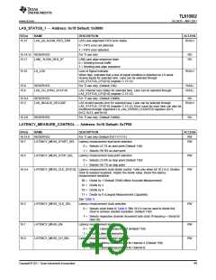
LAS_STATUS_1 — Address: 0x15 Default: 0x0000
BIT(s)
NAME
DESCRIPTION
ACCESS
15.15
LAS_LN_ALIGN_FIFO_ERR
LAS Lane alignment FIFO error status
0 = FIFO error not detected
1 = FIFO error detected
For TI use only
RO/LH
15.14:12 RESERVED
RO
RO
15.11
LAM_ ALIGN_SEQ_ST
LAM Lane align sequence state
0 = Sending normal traffic
1 = Sending lane align sequence
15.10
LS_LOS
Loss of Signal Indicator.
RO/LH
When high, indicates that a loss of signal condition is detected on LS serial
receive inputs for selected lane. Lane can be selected through
LAS_STATUS_CFG[1:0] (register C.13:12)
15.9
15.8
RESERVED
For TI use only. (Default 1’b0).
RO/LL
RO/LL
LAS_CH_SYNC_STATUS
LAS Channel sync status for selected lane. Lane can be selected through
LAS_STATUS_CFG[1:0] (register C.13:12)
15.6:4
15.3
RESERVED
For TI use only. (Default 2’b000).
RO
LAS_INVALID_DECODE
LAS Invalid decode error for selected lane. Lane can be selected through
RO/LH
LAS_STATUS_CFG[1:0] (register C.13:12). Error count for each lane can also be
monitored through respective LS_LNx_ERROR_COUNTER registers (0x11,
0x12, 0x13, and 0x14)
15.2:0
RESERVED
For TI use only. (Default 2’b000).
RO
LATENCY_MEASURE_CONTROL — Address: 0x16 Default: 0x7F00
BIT(s)
16.15:8
16.7
NAME
DESCRIPTION
ACCESS
RW
RESERVED
For TI use only (Default 8'b11111111)
LATENCY_MEAS_START_SEL Latency measurement start point selection
0 = Selects LS TX as start point (Default 1’b0)
RW
1 = Selects HS RX as start point
16.6
LATENCY_MEAS_STOP_SEL
Latency measurement stop point selection
0 = Selects LS RX as stop point (Default 1’b0)
1 = Selects HS TX as stop point
RW
RW
16.5:4
LATENCY_MEAS_CLK_DIV[1:0] Latency measurement clock divide control. Valid only when bit 16.2 is 0. Divides
clock to needed resolution. Higher the divide value, lesser the latency
measurement resolution
00 = Divide by 1 (Default 2’b00) (Most Accurate Measurement)
01 = Divide by 2
10 = Divide by 4
11 = Divide by 8 (Longest Measurement Capability)
See Table 9
16.2
LATENCY_MEAS_CLK_SEL
Latency measurement clock selection.
RW
0 = Selects clock listed in Table 9. Bits 16.5:4 can be used to divide this
clock to achieve needed resolution. (Default 1’b0)
1 = Selects respective channel recovered byte clock (Frequency = Serial bit
rate/ 20).
16.1
16.0
LATENCY_MEAS_EN
Latency measurement enable
RW
RW
0 = Disable Latency measurement (Default 1’b0)
1 = Enable Latency measurement
LATENCY_MEAS_CH_SEL
Latency measurement channel selection
0 = Selects Latency measurement for channel A (Default 1’b0)
1 = Selects Latency measurement for channel B
Copyright © 2011, Texas Instruments Incorporated
49

 TI [ TEXAS INSTRUMENTS ]