TLK10002
SLLSE75 –MAY 2011
www.ti.com
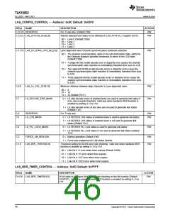
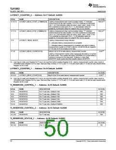
LAS_CONFIG_CONTROL — Address: 0x0C Default: 0x03F0
BIT(s)
NAME
DESCRIPTION
ACCESS
RW
C.15:14 RESERVED
For TI use only. (Default 2’b0)
C.13:12 LAS_STATUS_CFG[1:0]
Selects selected lane status to be reflected in LAS_STATUS_1 register (0x15)
RW
00 = Lane 0 (Default 2’b00)
01 = Lane 1
10 = Lane 2
11 = Lane 3
C.11:10 LAS_CH_SYNC_HYS_SEL[1:0]
Lane alignment slave Channel synchronization hysteresis selection
RW
00 = The channel synchronization, when in the synchronization state, performs
the Ethernet standard specified hysteresis to return to the LOS state
(Default 2’b00)
01 = A single 8b/10b invalid decode error or disparity error causes the channel
synchronization state machine to immediately transition from sync to LOS
10 = Two adjacent 8b/10b invalid decode errors or disparity errors cause the
channel synchronization state machine to immediately transition from sync
to LOS
11 = Three adjacent 8b/10b invalid decode errors or disparity errors cause the
channel synchronization state machine to immediately transition from sync
to LOS
C.9:8
C.7
LAS_LA_COL_CFG[1:0]
Minimum distance between align character in Lane alignment slave
RW
RW
00 =
8
01 = 16
1x = 24 (Default 2’b11)
LS_DECODE_ERR_MASK
0 = LS side decode errors of enabled lanes are used to generate link status if
error rate exceeds threshold. Valid only when hardware BER function is
enabled by setting A.13 to 1'b1.
1 = LS side decode errors of any lane are not used to generate link status
(Default 1’b1)
C.6
C.5
RESERVED
For TI use only.
RW
RW
LS_LOS_MASK
0 = LS SERDES LOS status of enabled lanes is used to generate link status
1 = LS SERDES LOS status of enabled lanes is not used to generate link
status (Default 1’b1)
C.4
LS_PLL_LOCK_MASK
0 = LS SERDES PLL Lock status is used to generate link status
RW
1 = LS SERDES PLL Lock status is not used to generate link status (Default
1’b1)
C.2
FORCE_LM_REALIGN
LAS_BER_THRESH[1:0]
0 = Normal operation (Default 1’b0)
RW
RW
1 = Force lane realignment in Link status monitor
C.1:0
Threshold setting for 8b/10b error rate checking. Valid only when hardware BER
function is enabled by setting A.13 to 1'b1.
00 = Link Ok if <1 error when timer expires (Default 2’b00)
01 = Link Ok if <15 error when timer expires
10 = Link Ok if <127 error when timer expires
11 = Link Ok if <1023 error when timer expires
LAS_BER_TMER_CONTROL — Address: 0x0D Default: 0xFFFF
BIT(s)
NAME
DESCRIPTION
ACCESS
D.15:0 LAS_BER_TIMER[15:0]
16 bit value to configure 8b/10b error rate checking on the link monitor (Default
16’hFFFF). Valid only when hardware BER function is enabled by setting A.13 to
1'b1.
RW
46
Copyright © 2011, Texas Instruments Incorporated

 TI [ TEXAS INSTRUMENTS ]