TLK10002
www.ti.com
SLLSE75 –MAY 2011
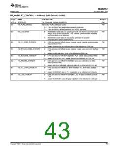
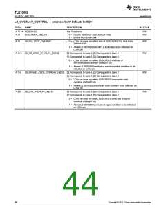
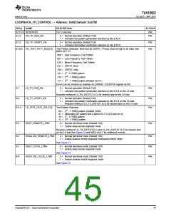
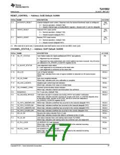
RESET_CONTROL — Address: 0x0E Default: 0x0000
BIT(s) NAME
DESCRIPTION
ACCESS
E.3
DATAPATH_RESET
Channel datapath reset control. Required once the desired functional mode is configured.
RW
SC(1)
0 = Normal operation. (Default 1’b0)
1 = Resets channel logic excluding MDIO registers. (Resets both Tx and Rx datapath)
E.2
TXFIFO_RESET
RXFIFO_RESET
Transmit FIFO reset control
RW
SC(1)
0 = Normal operation. (Default 1’b0)
1 = Resets transmit datapath FIFO.
Receive FIFO reset control
E.1
RW
SC(1)
0 = Normal operation. (Default 1’b0)
1 = Resets receive datapath FIFO.
(1) After reset bit is set to one, it automatically sets itself back to zero on the next MDC clock cycle.
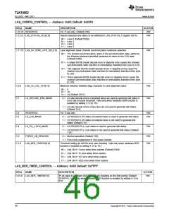
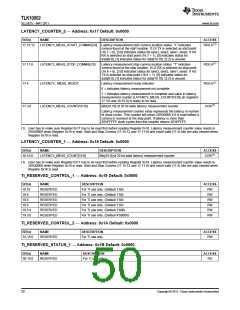
CHANNEL_STATUS_1 — Address: 0x0F Default: 0x0000
BIT(s) NAME
DESCRIPTION
ACCESS
F.15
HS_TP_ STATUS
Test Pattern status for High/Low/Medium/CRPAT test patterns
0 = Alignment has not achieved
RO
1 = Alignment has been determined and correct pattern has been received. Any bit errors
are reflected in HS_ERROR_COUNTER register (0x10)
F.14
F.13
LA_SLAVE_STATUS
HS_LOS
Lane alignment slave status
0 = Lane alignment is not achieved on the slave side
1 = Lane alignment is achieved on the slave side
RO/LL
RO/LH
Loss of Signal Indicator.
When high, indicates that a loss of signal condition is detected on HS serial receive
inputs
F.12
F.11
F.10
HS_AZ_DONE
Auto zero complete indicator.
When high, indicates auto zero calibration is complete
RO/LL
RO/LL
RO/LL
HS_AGC_LOCKED
HS_CHANNEL_SYNC
Adaptive gain control loop lock indicator.
When high, indicates AGC loop is in locked state
Channel synchronization status indicator.
When high, indicates channel synchronization has achieved
F.9
F.8
RESERVED
For TI use only. (Default 1’b0).
RO/LH
RO/LH
HS_DECODE_INVALID
Valid when decoder is enabled and during CRPAT test pattern verification.
When high, indicates decoder received an invalid code word, or a 8b/10b disparity error.
In functional mode, number of DECODE_INVALID errors are reflected in
HS_ERROR_COUNTER register (0x10)
F.7
F.6
F.5
F.4
F.3
TX_FIFO_UNDERFLOW
TX_FIFO_OVERFLOW
RX_FIFO_UNDERFLOW
RX_FIFO_OVERFLOW
RX_LS_OK
When high, indicates underflow has occurred in the transmit datapath FIFO.
When high, indicates overflow has occurred in the transmit datapath FIFO.
When high, indicates underflow has occurred in the receive datapath FIFO.
When high, indicates overflow has occurred in the receive datapath FIFO.
RO/LH
RO/LH
RO/LH
RO/LH
RO/LL
Receive link status indicator from LS side.
When high, indicates receive link status is achieved on the LS side
F.2
F.1
TX_LS_OK
Link status indicator from Link training slave inside TLK10002
When high, indicates Link training slave has achieved sync and alignment
RO/LL
RO/LL
LS_PLL_LOCK
LS SERDES PLL lock indicator
When high, indicates LS SERDES PLL is locked to the selected incoming
REFCLK0/1_P/N
F.0
HS_PLL_LOCK
HS SERDES PLL lock indicator
RO/LL
When high, indicates HS SERDES PLL is locked to the selected incoming
REFCLK0/1_P/N
Copyright © 2011, Texas Instruments Incorporated
47

 TI [ TEXAS INSTRUMENTS ]