TLK10002
SLLSE75 –MAY 2011
www.ti.com
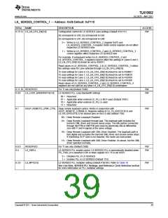
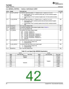
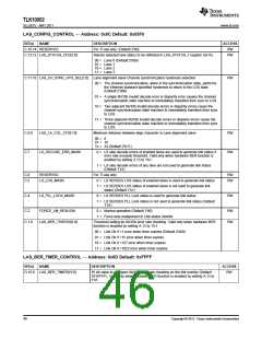
LS_ SERDES_CONTROL — Address: 0x08 Default: 0x0001
BIT(s)
NAME
DESCRIPTION
ACCESS
8.15
LS_OUT_INVPAIR
LS SERDES output lane polarity. (x = Channel A or B, y = Lane 0 or 1 or 2 or 3)
RW
0 = Normal polarity. OUTxyP considered positive data. OUTxyN considered negative
data (Default 1’b0)
1 = Inverted polarity. OUTxyP considered negative data. OUTxyN considered positive
data
8.14
LS_IN_INVPAIR
LS SERDES input lane polarity. (x = Channel A or B, y = Lane 0 or 1 or 2 or 3)
RW
0 = Normal polarity. INxyP considered positive data and INxyN considered negative
data (Default 1’b0)
1 = Inverted polarity. INxyP considered negative data and INxyP considered positive
data
8.13:12 RESERVED
For TI use only (Default 2’b00)
RW
RW
RW
RW
8.11:8
8.7
LS_EQ[3:0]
RESERVED
LS_CDR[2:0]
LS SERDES Equalization control (Default 4’b0000). Refer to Table 19.
For TI use only (Default 1’b0)
8.6:4
LS SERDES CDR control (Default 3’b000)
000 – 1st Order. Threshold of 1
001 – 1st Order. Threshold of 17
010 – 2nd Order. High precision. Threshold of 1
011 – 2nd Order. High precision. Threshold of 17
100 – 1st Order. Low precision. Threshold of 1
101 – 2nd Order. Low precision. Threshold of 17
11x – Reserved
8.3
LS_TX_ENTEST
LS_RX_ENTEST
RESERVED
LS SERDES test mode control on the channel input
RW
RW
RW
0 = Normal operation (Default 1’b0)
1 = Enable test mode
8.2
LS SERDES test mode control on the channel output
0 = Normal operation (Default 1’b0)
1 = Enable test mode
8.1:0
For TI use only (Default 2’b01)
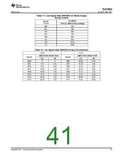
Table 19. Low Speed Side SERDES Equalization
8.11:8
Low Freq Gain
Maximum
8.11:8
Value
Zero Freq
Value
1000
1001
1010
1011
1100
1101
1110
1111
Low Freq Gain
Zero Freq
0000
0001
0010
0011
0100
0101
0110
0111
365 MHz
275 MHz
195 MHz
140 MHz
105 MHz
75 MHz
Adaptive
Adaptive
Reserved
55 MHz
50 MHz
42
Copyright © 2011, Texas Instruments Incorporated

 TI [ TEXAS INSTRUMENTS ]