TLK10002
SLLSE75 –MAY 2011
www.ti.com
Test Pattern Generation and Verification
The TLK10002 has an extensive suite of built in test functions to support system diagnostic requirements. Each
channel has sets of internal test pattern generators and verifiers.
Several patterns can be selected via the MDIO interface that offer extensive test coverage. The low speed side
supports generation and verification of pseudo-random bit sequence (PRBS) 27-1, 223-1, and 231-1 patterns. In
addition to those PRBS patterns, the high speed side supports High-frequency (HF), Low-frequency (LF),
Mixed-frequency (MF), and continuous random test pattern (CRPAT) long/short pattern generation and
verification as defined in Annex 48A of the IEEE Standard 802.3ae-2002. Use of CRPAT verifier requires
checking TPsync (MDIO register bit F.15).
The TLK10002 provides two pins: PRBSEN and PRBS_PASS, for additional and easy control and monitoring of
PRBS pattern generation and verification. When the PRBSEN is asserted high, the internal PRBS generator and
verifier circuits are enabled on both transmit and receive data paths on high speed and low speed sides of both
channels. This signal is logically OR’d with an MDIO register bits B.7:6 and B.13:12.
PRBS 231-1 is selected by default, and can be changed through MDIO.
When PRBS test is enabled (PRBSEN=1):
•
•
PRBS_PASS=1 indicates that PRBS pattern reception is error free.
PRBS_PASS=0 indicates that a PRBS error is detected. The channel, the side (high speed or low speed),
and the lane (for low speed side) that this signal refers to is chosen through MDIO register bit 0.3:0.
Latency Measurement Function
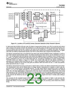
The TLK10002 includes a latency measurement function to support CPRI and OBSAI base station applications.
There are two start and two stop locations for the latency counter as shown in Figure 16 for Channel A. The start
and stop locations are selectable through MDIO register bits 0x16.7 and 0x16.6 respectively. The elapsed time
from a comma detected at an assigned counter start location of a particular channel to a comma detected at an
assigned counter stop location of the same channel is measured and reported through the MDIO interface. The
function operates on one channel at a time. The following three control characters (containing commas) are
monitored:
1. K28.1 (control = 1, data = 0x3C)
2. K28.5 (control = 1, data = 0xBC)
3. K28.7 (control = 1, data = 0xFC).
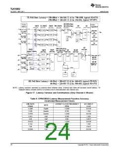
The first comma found at the assigned counter start location will start up the latency counter. The first comma
detected at the assigned counter stop location will stop the latency counter. The 20-bit latency counter result of
this measurement is readable through the MDIO interface through register bits 0x17.3:0 and 0x18.15:0. The
accuracy of the measurement is a function of the serial bit rate at which the channel being measured is
operating. The register will return a value of 0xFFFF if the duration between transmit and receive comma
detection exceeds the depth of the counter. Only one measurement value is stored internally until the 20-bit
results counter is read. The counter will return zero in cases where a transmit comma was never detected
(indicating the results counter never began counting).
22
Copyright © 2011, Texas Instruments Incorporated

 TI [ TEXAS INSTRUMENTS ]