TLK10002
www.ti.com
SLLSE75 –MAY 2011
Chan nel A
10
10
10
10
10
10
10
10
32
16
16
INA0P/N
LS PRBS
Verifier
TX FIFO
HS PRBS
Generator
HSTXAP /N
16
20
INA1P/N
INA2P/N
Pattern
Generator
INA3P/N
Stop
Counter
Start
Counter
High
Speed
Side
Transmit Data Path Covered
Low
Speed
Laten cy
Count er
SERDES
Side
SERDES
Receive Data Path Covered
Stop
Counter
Start
Counter
10
10
10
HS PRBS
Verifier
16
20
32
OUTA0P/N
OUTA1P/N
HSRXAP /N
RX FIFO
10
10
1
0
LS PRBS
Generator
OUTA2P/N
OUTA3P/N
10
10
Pattern
Verifier
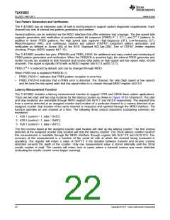
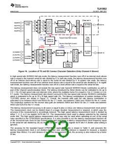
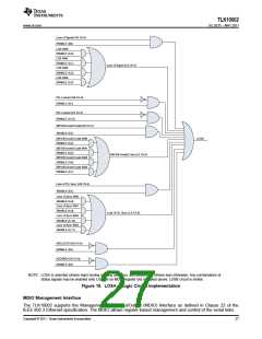
Figure 16. Location of TX and RX Comma Character Detection (Only Channel A Shown)
In high speed side SERDES full rate mode, the latency measurement function runs off of an internal clock whose
rate is equal to the transmit serial bit rate divided by 8. In half rate mode, the latency measurement function runs
off of an internal clock whose rate is equal to the serial bit rate divided by 4. In quarter rate mode, the latency
measurement function runs off of an internal clock whose rate is equal to the serial bit rate divided by 2. In eighth
rate mode, the latency measurement function runs off of a clock whose rate is equal to the serial bit rate.
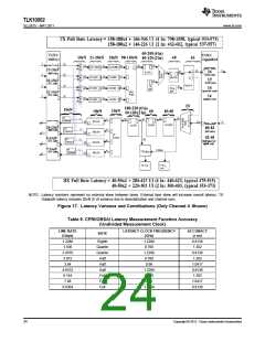
The latency measurement does not include the low speed side transmit SERDES blocks contribution as well as
part of the channel synchronization block. The latency introduced by these blocks can be estimated to be up to
(18 + 10) x N high speed side unit intervals (UIs), where the multiplex factor N is equal to 2 (in 2:1 mode) or 4 (in
4:1 mode). The latency measurement also doesn’t account for the low speed side receive SERDES contribution
which is estimated to be up to 20 x N high speed side UIs. The latency contributions of various sections of the
TLK10002 device are shown in Figure 15. Overall, the transmit data path full rate latency contribution is
estimated to be between 462UI and 602UI for the 2:1 mode, and between 798UI and 1058UI for the 4:1 mode.
The respective numbers for the receive data path are between 300UI and 403UI for the 2:1 mode and between
440UI and 623UI for the 4:1 mode.
The latency measurement accuracy in all cases is equal to plus or minus one latency measurement clock period.
The measurement clock can be divided down if a longer duration measurement is required, in which case the
accuracy of the measurement is accordingly reduced. The high speed latency measurement clock is divided by
either 1, 2, 4, or 8 via register 0x16 bits 5:4. The measurement clock used is always selected by the channel
under test. The high speed latency measurement clock may only be used when operating at one of the serial
rates specified in the CPRI/OBSAI specifications. It is also possible to run the latency measurement function off
of the recovered byte clock for the channel under test (and gives a latency measurement clock frequency equal
to the serial bit rate divided by 20) via register 0x16 bit 2 (where the register 0x16 bits 5:4 divider value setting is
ignored).
The accuracy for the standard based CPRI/OBSAI application rates is shown in Table 9, and assumes the
latency measurement clock is not divided down per user selection (division is required to measure a duration
greater than 682us). For each division of two in the measurement clock, the accuracy is also reduced by a factor
of two.
Copyright © 2011, Texas Instruments Incorporated
23

 TI [ TEXAS INSTRUMENTS ]