TLK10002
SLLSE75 –MAY 2011
www.ti.com
Loss of Signal Indication (LOS)
Loss of input signal detection is based on the voltage level of each serial input signal INA*P/N, INB*P/N,
HSRXAP/N, and HSRXBP/N. When LOS indication is enabled and a channel's differential serial receive input
level is < 75mVpp, that channel's respective LOS indicator (LOSA or LOSB) will be asserted (high true). If the
input signal is >150mVpp, the LOS indicator will be deasserted (low false). Outside of these ranges, the LOS
indication is undefined. The LOS indicators are also directly readable through the MDIO interface.
The following additional critical status conditions can be combined with the loss of signal condition enabling
additional real-time status signal visibility on the LOSA and LOSB outputs per channel:
1. Loss of Channel Synchronization Status – Logically OR’d with LOS condition(s) when enabled. Loss of
channel synchronization can be optionally logically OR’d (disabled by default) with the internally generated
LOS condition (per channel).
2. Loss of PLL Lock Status on LS and HS sides – Logically OR’d with LOS condition(s) when enabled. The
internal PLL loss of lock status bit is optionally OR’d (disabled by default) with the other internally generated
loss of signal conditions (per channel).
3. Receive 8B/10B Decode Error (Invalid Code Word or Running Disparity Error) – Logically OR’d with LOS
condition(s) when enabled. The occurrence of an 8B/10B decode error (invalid code word or disparity error)
is optionally OR’d (disabled by default) with the other internally generated loss of signal conditions (per
channel).
4. AGCLOCK (Active Gain Control Currently Locked) – Inverted and Logically OR’d with LOS condition(s) when
enabled. HS RX SERDES adaptive gain control unlocked indication is optionally OR’d (disabled by default)
with the other internally generated loss of signal conditions (per channel).
5. AZDONE (Auto Zero Calibration Done) – Inverted and Logically OR’d with LOS conditions(s) when enabled.
HS RX SERDES auto-zero not done indication is optionally OR’d (disabled by default) with the other
internally generated loss of signal conditions (per channel).
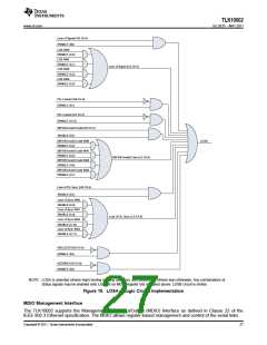
Figure 19 shows the detailed implementation of the LOSA signal along with the associated MDIO control
registers.
26
Copyright © 2011, Texas Instruments Incorporated

 TI [ TEXAS INSTRUMENTS ]