TLK10002
www.ti.com
SLLSE75 –MAY 2011
Power Down Mode
The TLK10002 can be put in power down either through device inputs pins or through MDIO control register
(1.15).
PDTRXA_N: Active low, powers down channel A.
PDTRXB_N: Active low, powers down channel B.
The MDIO management serial interface remains operational when in register based power down mode (1.15
asserted for both channels), but status bits may not be valid since the clocks are disabled. The low speed side
and high speed side SERDES outputs are high impedance when in power down mode. Please see the detailed
per pin description for the behavior of each device I/O signal during pin based and register based power down.
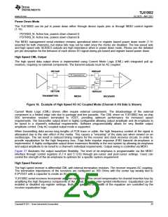
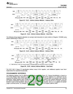
High Speed CML Output
The high speed data output driver is implemented using Current Mode Logic (CML) with integrated pull up
resistors, requiring no external components. The transmit outputs must be AC coupled.
HSTXAP
HSRXAP
50 W transmission line
50 W
0.8*VDDT
50 W
GND
50 W transmission line
HSTXAN
HSRXAN
TRANSMITTER
MEDIA
RECEIVER
Figure 18. Example of High Speed I/O AC Coupled Mode (Channel A HS Side is Shown)
Current Mode Logic (CML) drivers often require external components. The disadvantage of the external
component is a limited edge rate due to package and line parasitic. The CML driver on TLK10002 has on-chip
50Ω termination resistors terminated to VDDT, providing optimum performance for increased speed
requirements. The transmitter output driver is highly configurable allowing output amplitude and de-emphasis to
be tuned to a channel's individual requirements. Software programmability allows for very flexible output
amplitude control. Only AC coupled output mode is supported.
When transmitting data across long lengths of PCB trace or cable, the high frequency content of the signal is
attenuated due to the skin effect of the media. This causes a “smearing” of the data eye when viewed on an
oscilloscope. The net result is reduced timing margins for the receiver and clock recovery circuits. In order to
provide equalization for the high frequency loss, 3-tap finite impulse response (FIR) transmit de-emphasis is
implemented. A highly configurable output driver maximizes flexibility in the end system by allowing de-emphasis
and output amplitude to be tuned to a channel’s individual requirements. Output swing is controlled via MDIO.
Figure 27 illustrates the output waveform flexibility. The level of de-emphasis is programmable via the MDIO
interface through control registers (5.7:4 and 5.12:8) through pre-cursor and post-cursor settings. Users can
control the strength of the de-emphasis to optimize for a specific system requirement.
High Speed Receiver
The high speed receiver is differential CML with internal termination resistors. The receiver requires AC coupling.
The termination impedances of the receivers are configured as 100 Ohms with the center tap weakly tied to
0.8*VDDT with a capacitor to create an AC ground.
TLK10002 serial receivers incorporate adaptive equalizers. This circuit compensates for channel insertion loss by
amplifying the high frequency components of the signal, reducing inter-symbol interference. Equalization can be
enabled or disabled via register settings. Both the gain and bandwidth of the equalizer are controlled by the
receiver equalization logic.
Copyright © 2011, Texas Instruments Incorporated
25

 TI [ TEXAS INSTRUMENTS ]