THS4631
www.ti.com
SLOS451A–DECEMBER 2004–REVISED MARCH 2005
this corner frequency properly leads to more accurate
measurements of the transimpedance bandwidth. If
the interface circuit corner frequency is too close to
the bandwidth of the circuit, determining the power
level in the flatband is difficult. A decade or more of
flat bandwidth provides a good basis for determining
the proper transimpedance bandwidth.
R
F2
R
+ R
1 )
ǒ Ǔ
EQ
F1
R
F3
(5)
C
F
R
F3
R
F2
R
F1
ALTERNATIVE TRANSIMPEDANCE
CONFIGURATIONS
_
+
λ
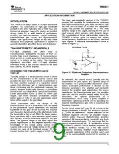
Other transimpedance configurations are possible.
Three possibilities are shown below.
R
L
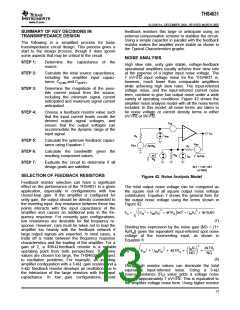
The first configuration is a slight modification of the
basic transimpedance circuit. By splitting the
feedback resistor, the feedback capacitor value be-
comes more manageable and easier to control. This
type of compensation scheme is useful when the
feedback capacitor required in the basic configuration
becomes so small that the parasitic effects of the
board and components begin to dominate the total
feedback capacitance. By reducing the resistance
across the capacitor, the capacitor value can be
increased. This mitigates the dominance of the para-
sitic effects.
−V
(Bias)
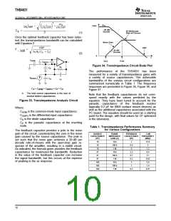
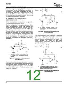
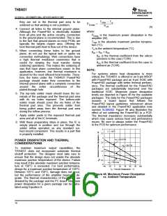
A.
A
resistive T-network enables high
transimpedance gain with reasonable re-
sistor values.
Figure 40. Alternative Transimpedance
Configuration 2
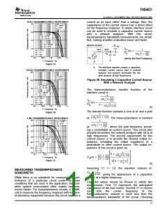
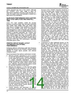
The third configuration uses a capacitive T-network to
achieve fine control of the compensation capacitance.
The capacitor CF3 can be used to tune the total
effective feedback capacitance to a fine degree. This
circuit behaves
the same as
the basic
C
F
transimpedance configuration, with the effective CF
given by Equation 6.
R
F2
R
F1
C
F3
1
1
+
1 )
ǒ Ǔ
_
+
λ
C
C
C
FEQ
F1
F2
(6)
R
L
C
F3
−V
(Bias)
C
F1
C
F2
A. Splitting the feedback resistor enables use
of a larger, more manageable feedback
capacitor.
R
F
_
+
Figure 39. Alternative Transimpedance
Configuration 1
λ
R
L
The second configuration uses a resistive T-network
to achieve high transimpedance gains using relatively
small resistor values. This topology can be useful
when the desired transimpedance gain exceeds the
value of available resistors. The transimpedance gain
is given by Equation 5.
−V
(Bias)
A. A capacitive T-network enables fine control
of the effective feedback capacitance using
relatively large capacitor values.
Figure 41. Alternative Transimpedance
Configuration 3
12

 TI [ TEXAS INSTRUMENTS ]