SN65HVS883
www.ti.com.cn
ZHCSFI0 –SEPTEMBER 2016
9 Application and Implementation
NOTE
Information in the following applications sections is not part of the TI component
specification, and TI does not warrant its accuracy or completeness. TI’s customers are
responsible for determining suitability of components for their purposes. Customers should
validate and test their design implementation to confirm system functionality.
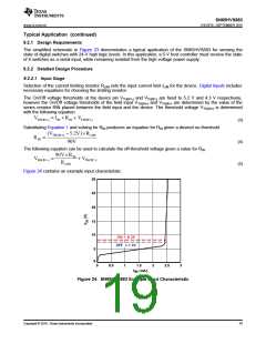
9.1 Application Information
9.1.1 System-Level EMC
The SN65HVS883 must operate reliably in harsh industrial environments. At a system level, the device is tested
according to several international electromagnetic compatibility (EMC) standards.
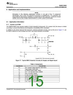
In addition to the device internal ESD structures, external protection circuitry, such as the one in Figure 17, can
be used to absorb as much energy from burst- and surge-transients as possible.
C
C
R
D
RP
S
V
SUP
= 24 V
V24
D
D
Z
C
TS
C
C
C
C
HV
C
B
SN65HVS883
R
IN
INx
IP0 – IP7
FGND
C
IN
0 V
C
HV
FE
Copyright © 2016, Texas Instruments Incorporated
Figure 17. Typical EMC Protection Circuitry for Supply and Signal Inputs
Table 3. Components
DESIGNATOR
DESCRIPTION
DTS
39 V Transient Voltage Suppressor: SM15T39CA
Super Rectifier: BYM10-1000,
or General Purpose rectifier: 1N4007
DRP
DZ
RS
33 V – 36 V fast Zener Diode, Z2SMB36
56 Ω, 1/3 W MELF Resistor
RIN
CIN
CHV
CC
1.2 kΩ, 1/4 W MELF Resistor
22 nF, 60 V Ceramic Capacitor
4.7 nF, 2 kV Ceramic Capacitor
n x 220 nF, 60 V Ceramic Capacitors
1 µF - 10 µF, 60 V Ceramic Capacitor
CB
Copyright © 2016, Texas Instruments Incorporated
15

 TI [ TEXAS INSTRUMENTS ]