SN65HVS883
www.ti.com.cn
ZHCSFI0 –SEPTEMBER 2016
Typical Application (continued)
9.2.1 Design Requirements
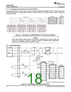
The simplified schematic in Figure 23 demonstrates a typical application of the SN65HVS883 for sensing the
state of digital switches with 24-V high logic levels. In this application, a 5-V host controller must receive the state
of 8 switches as a serial input, while remaining isolated from the high voltage power supply.
9.2.2 Detailed Design Procedure
9.2.2.1 Input Stage
Selection of the current limiting resistor RLIM sets the input current limit ILIM for the device. Digital Inputs includes
necessary equations for choosing the limiting resistor.
The On/Off voltage thresholds at the device pin VTH(IP+) and VTH(IP-) are fixed to 5.2 V and 4.3 V respectively,
however the On/Off voltage thresholds of the field input VTH(IN+) and VTH(IN-) are determined by the value of the
series resistor RIN placed between the field input and the device. The threshold voltage VTH(IN+) is determined
with the following equation:
VTH(IN+) = IIN ´RIN + VTH(IP+)
(3)
Substituting Equation 1 and solving for RIN produces an equation for RIN given a desired on-threshold.
(VTH(IN+) -5.2V)´RLIM
RIN =
90V
(4)
(5)
The following equation can be used to calculate the off-threshold voltage given a value for RIN
90V´RIN
VTH(IN-)
=
+ VTH(IP-)
RLIM
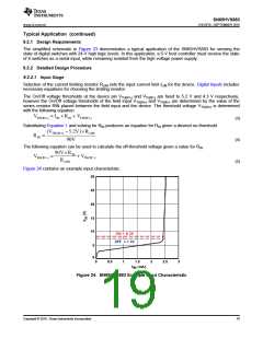
Figure 24 contains an example input characteristic:
30
25
20
15
10
ON = 8.2V
OFF = 7.3V
5
0
0
0.5
1
1.5
(mA)
2
2.5
3
I
IN
Figure 24. SN65HVS883 Example Input Characteristic
Copyright © 2016, Texas Instruments Incorporated
19

 TI [ TEXAS INSTRUMENTS ]