SN65HVS883
ZHCSFI0 –SEPTEMBER 2016
www.ti.com.cn
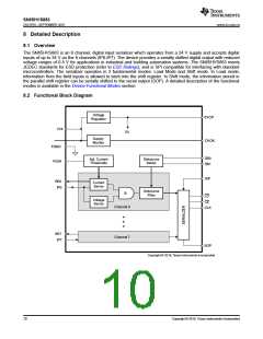
8.4 Device Functional Modes
The 2 functional modes of operation are Load mode and Shift mode.
Load mode enables information from the field inputs to latch into the shift register. To enter load mode, the LD
pin must be held low, and the device remains in load mode regardless of the CLK, CE, or serial (SIP) input
levels. A high level at the LD pin switches the device into Shift mode.
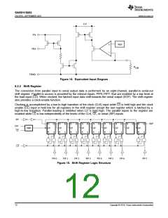
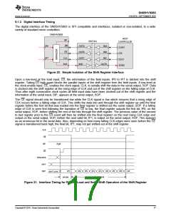
When the device is in Shift mode, a low level at the CE pin causes the data stored in all registers of the parallel
shift register except for the last register, to be serially shifted toward the serial output (SOP) on the rising edge of
CLK. The final register in the shift register will be shifted toward the serial output (SOP) on the falling edge of
CLK. A high level at the CE pin inhibits the serial shifting, which is demonstrated in Figure 21. After 8
consecutive CLK cycles, the serial output (SOP) remains at the level of the serial input (SIP) which is internally
pulled to logic high. A logic high at the CE pin is required to signify the end of the serial data output. For of a
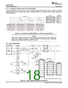
daisy chained configuration, the serial output (SOP) of the SN65HVS883 can be connected to the serial input
(SIP) of a following device, and additional clock cycles are required to shift the additional data out of the chain.
The number of consecutive clock cycles will equal 8 times the number of devices in the chain. See Figure 22 for
an example of a cascaded chain of 4x SN65HVS883.
14
Copyright © 2016, Texas Instruments Incorporated

 TI [ TEXAS INSTRUMENTS ]