SN65HVS883
www.ti.com.cn
ZHCSFI0 –SEPTEMBER 2016
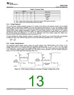
Table 2. Function Table
INPUTS
FUNCTION
LD
L
CLK
CE
X
X
X
↑
Parallel load
No change
Shift(1)
H
H
L
H
H
↓
L
Shift(2)
(1) Shift = content of each internal register, except the last register, shifts towards serial output.
(2) Shift = content of the last register shifts towards serial output.
8.3.4 Voltage Regulator
The on-chip linear voltage regulator provides a 5 V supply to the internal- and external circuitry, such as digital
isolators, with an output drive capability of 50 mA and a typical current limit of 115 mA. The regulator accepts
input voltages from 34 V down to 10 V. Because the regulator output is intended to supply external digital isolator
circuits proper output voltage decoupling is required. For best results connect a 1 μF and a 0.1 μF ceramic
capacitor as close as possible to the 5VOP-output. For longer traces between the SN65HVS883 and isolators of
the ISO72xx family use additional 0.1 μF and 10 pF capacitors next to the isolator supply pins. Make sure,
however, that the total load capacitance does not exceed 4.7 μF.
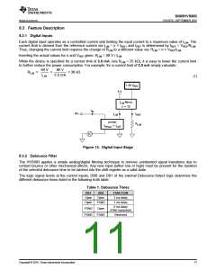
For good stability the voltage regulator requires a minimum load current, IL-MIN. Ensure that under any operating
condition the ratio of the minimum load current in mA to the total load capacitance in μF is larger than 1:
I
1 mA
1 µF
L-MIN
>
C
L
(2)
8.3.5 Supply Voltage Monitor
The integrated supply voltage monitor senses the supply voltage of the SN65HVS883 at the V24-pin. If this
voltage drops below 15 V but stays within the regulator’s operating range, i.e., 15 V > V24 > 10 V, the output
CHOK goes low 1 ms later. When the supply voltage returns to 24 V, the CHOK output turns logic high after
6 ms. Should the supply voltage drop below 10 V, the device ceases operation. Upon the supply returning to
above 18 V, the CHOK output turns high again after 6 ms.
18 V
18 V
15 V
15 V
10 V
V24 < 10 V
V24
15 V > V24 > 10 V
1 ms
debounce
time starts
1 ms
debounce
time starts
t
t
DB-LH
t
DB-LH
DB-HL
Circuit ceases
operation
CHOK
Figure 16. CHOK Output Timing as a Function of Supply Voltage Drop at V24
Copyright © 2016, Texas Instruments Incorporated
13

 TI [ TEXAS INSTRUMENTS ]