SN65HVS883
www.ti.com.cn
ZHCSFI0 –SEPTEMBER 2016
8.3 Feature Description
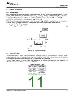
8.3.1 Digital Inputs
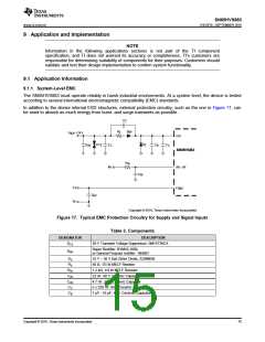
Each digital input operates as a controlled current sink limiting the input current to a maximum value of ILIM. The
current limit is derived from the reference current via ILIM = n × IREF, and IREF is determined by IREF = VREF/RLIM
Thus, changing the current limit requires the change of RLIM to a different value via: RLIM = n × VREF/ILIM
.
.
Inserting the actual values for n and VREF gives: RLIM = 90 V / ILIM
.
While the device is specified for a current limit of 3.6 mA, (via RLIM = 25 kΩ), it is easy to lower the current limit
to further reduce the power consumption. For example, for a current limit of 2.5 mA simply calculate:
90 V
90 V
RLIM
=
=
= 36 kΩ
ILIM
2.5 mA
(1)
1.25 V
REF
5 V
I
Mirror
LIM
n = 72
I
IN
IPx
I
I
REF
LIM
Limiter
= I
R
LIM
I
INmax
LIM
Figure 13. Digital Input Stage
8.3.2 Debounce Filter
The HVS883 applies a simple analog/digital filtering technique to remove unintended signal transitions due to
contact bounce or other mechanical effects. Any new input (either low or high) must be present for the duration
of the selected debounce time to be latched into the shift register as a valid state.
The logic signal levels at the control inputs, DB0 and DB1 of the internal Debounce-Select logic determine the
different debounce times listed in the following truth table.
Table 1. Debounce Times
DB1
Open
Open
DB0
Open
FGND
FUNCTION
3 ms delay
1 ms delay
0 ms delay
(Filter bypassed)
FGND
FGND
Open
FGND
Reserved
Copyright © 2016, Texas Instruments Incorporated
11

 TI [ TEXAS INSTRUMENTS ]