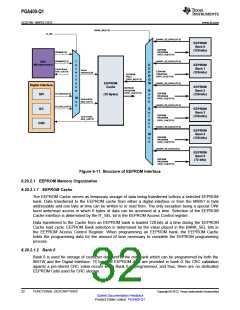
PGA400-Q1
SLDS186 –MARCH 2012
www.ti.com
6.25 Diagnostics
This section describes the diagnostics.
6.25.1 Power Supply Diagnostics
The device includes modules to monitor the power supply for faults. The internal power rails that are
monitored are AVDD, DVDD, VBRG, and EEPROM charge pump. Please refer to the electrical
specifications for the thresholds.
When a fault is detected, an appropriate bit in the PSMON1 and PSMON2 registers is set. If the faulty
condition is removed, the fault bits will remain latched. To remove the fault the 8051W software should
read the fault bit and write a logic zero back to the bit. In addition a system reset will clear the fault.
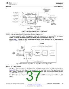
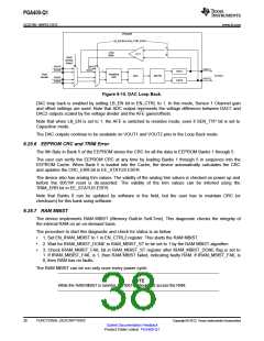
6.25.2 Resistive Bridge Sensor Connectivity Diagnostics
The device includes modules to monitor for sensor faults. Specifically, the device monitors the sensor pins
for opens (including loss of connection from the sensor), short-to-ground, and short to sensor supply.
When a fault is detected, an appropriate bit in the AFEDIAG register is set. All three types of sensor faults
will result in the setting of the same bit, meaning it is not possible to distinguish the type of fault that has
occured. Even after the faulty condition is removed, the fault bits remains latched. To remove the fault the
8051W software should read the fault bit and write a logic zero back to the bit. In addition a system reset
will clear the fault.
Open Sensor Faults are detected through the use of an internal pull-down resistor. The value of the
resistor can be configured using DIS_R1M and DIS_R2M bits in Decimator and Low Power Control
Register (DECCTRL) in the ESFR memory space. This configurability allows the detection of open sensor
faults for various Stage 1 Gain settings. For more information on programming this device please refer to
thePGA400-Q1 Programming Application Note (SLDA015).
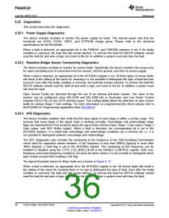
6.25.3 AFE Diagnostics
The device includes modules that verify that the input signal of each stage is within a certain range. This
ensures that every stage of the signal chain is working normally. Overvoltage and undervoltage range
flags are implemented in four locations along the signal chain (Sensor Input, Stage 1 Gain output, Stage 2
Gain output, and ADC Buffer output). When a fault is detected, the corresponding bit is set in the
AFEDIAG registers. It is noted both overvoltage and undervoltage conditions set a common bit; i.e., it is
not possible to distinguish between overvoltage and undervoltage.
The AFE Diagnostics also includes the monitoring of the frequency of the Self-Oscillating Demodulator
circuit used for capacitive sensor interface. If the frequency is less than 40KHz (typical) or more than
1MHz (typical), a fault flag is set in the AFEDIAG register. The monitoring of this frequency can be
enabled or disabled using the CTOV_CLK_MON_EN bit in the ENABLE CONTROL register. Both over-
frequency and under-frequency conditions set same bit which means it is not possible to distinguish which
type of fault occured that resulting in the flag.
The typical threshold values for these faults are in boxes in Figure 6-12.
When a fault is detected, an appropriate bit in the AFEDIAG register is set. All sensor faults will result in
the setting of the same bit, meaning there is no way to distinguish the type of fault. Even after the faulty
condition is removed, the fault bits will remain latched. To remove the fault the 8051W software should
read the fault bit and write a logic zero back to the bit. In addition a system reset will clear the fault.
36
FUNCTIONAL DESCRIPTIONS
Copyright © 2012, Texas Instruments Incorporated
Submit Documentation Feedback
Product Folder Link(s): PGA400-Q1

 TI [ TEXAS INSTRUMENTS ]