PGA400-Q1
www.ti.com
SLDS186 –MARCH 2012
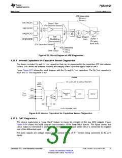
Figure 6-12. Block Diagram of AFE Diagnostics
6.25.4 Internal Capacitors for Capacitive Sensor Diagnostics
The device includes Cp and Cr Test capacitors that can be connected to the capacitive AFE via software
control. This allows the software to check the integrity of the capacitive signal chain in the IC.
Figure Figure 6-13 shows the block diagram with the Cp and Cr Test capacitors. The Cp Test capacitor is
10pF and Cr Test capacitor is 8pF.
PGA400
INT_CAPS_EN Bit in EN_CTRL ESFR
Input
Sensor
Select
CP1
CR1
+
-
From
Sensor
Capacitive
AFE
ADC
8051W
CP2
CR2
CPT
CRT
10pF
8pF
ICAP in CAPSEN ESFR
Figure 6-13. Internal Capacitors for Capacitive Sensor Diagnostics.
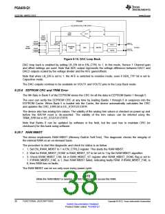
6.25.5 DAC Diagnostics
The device implements a “Loop Back” feature to check the integrity of the two DAC outputs. Figure
Figure 6-14 shows the block diagram representation of the Loop Back feature. This figure shows that
DAC1 output is connected to positive side of the differential input while DAC2 is connected to negative
side of the differential input.
The DAC outputs are voltage divided by a nominal factor of 6/11 before being connected to the AFE
inputs.
Copyright © 2012, Texas Instruments Incorporated
FUNCTIONAL DESCRIPTIONS
37
Submit Documentation Feedback
Product Folder Link(s): PGA400-Q1

 TI [ TEXAS INSTRUMENTS ]