PGA400-Q1
SLDS186 –MARCH 2012
www.ti.com
PGA400
LB_EN Bit in EN_CTRL ESFR
Loop
Back
6/11
Input
Sensor
Select
VIN1P
DAC1
DAC2
VOUT1
VOUT2
VIN1R
+
-
DAC1
DAC2
From
Sensor
Resistive
AFE
ADC
8051W
To ECU
VIN2P
VIN2R
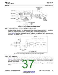
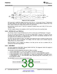
Figure 6-14. DAC Loop Back.
DAC loop back is enabled by setting LB_EN bit in EN_CTRL to 1. In this mode, Sensor 1 Channel gain
and offset settings are used. Note that ADC output represents the voltage difference between DAC1 and
DAC2 outputs scaled by the voltage divider and the AFE gains/offsets.
Note that when LB_EN is set to 1, the AFE is switched to resistive mode, even if SEN_TYP bit is set to
Capacitive mode.
The DAC outputs continue to be available on VOUT1 and VOUT2 pins in the Loop Back mode.
6.25.6 EEPROM CRC and TRIM Error
The 9th Byte in Bank 5 of the EEPROM stores the CRC for all the data in EEPROM Banks 1 through 5.
The user can verify the EEPROM CRC at any time by loading Banks 1 through 5 in sequence into the
EEPROM Cache. When Bank 5 is loaded into the Cache, the device automatically calculates the CRC
and updates the CRC_ERR bit in EE_STATUS ESFR.
The device also has analog trim values. The validity of the analog trim values is checked on power up and
before the 8051W reset is de-asserted. The validity of the trim values can be inferred using the
TRIM_ERR bit in EE_STATUS ESFR.
Note that Banks 0 can be updated by software in the field, but the user has to maintain CRC (or
checksum) for this bank using software.
6.25.7 RAM MBIST
The device implements RAM MBIST (Memory Built-In Self-Test). This diagnostic checks the integrity of
the internal RAM on an on-demand basis.
The procedure to start this diagnostic and check for status is as below:
•
•
•
1. Set EN_IRAM_MBIST to 1 in EN_CTRL2 register. This starts the RAM MBIST.
2. Wait for IRAM_MBIST_DONE in RAM_MBIST_ST to be set to 1 by the RAM MBIST algorithm
3. Check IRAM_MBIST_FAIL bit in RAM_MBIST_ST register after IRAM_MBIST_DONE flag is set to
1. If IRAM_MIBIST_FAIL is 1, then RAM MBIST failed, indicating faulty RAM. If IRAM_MBIST_FAIL is
0, then RAM has no faults.
The RAM MBIST can be run only once every power cycle.
NOTE
While the RAM MBIST is running, the 8051W should not access the RAM.
38
FUNCTIONAL DESCRIPTIONS
Copyright © 2012, Texas Instruments Incorporated
Submit Documentation Feedback
Product Folder Link(s): PGA400-Q1

 TI [ TEXAS INSTRUMENTS ]