PGA400-Q1
www.ti.com
SLDS186 –MARCH 2012
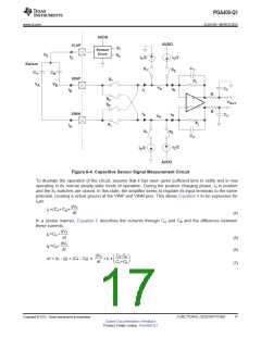
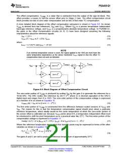
Figure 6-4. Capacitive Sensor Signal Measurement Circuit
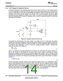
To illustrate the operation of the circuit, assume that it has been given sufficient time to settle and is now
operating in its normal steady-state mode of operation. During the positive charging phase, IX is positive
and the S1 switches are closed. In this state, the amplifier seeks to regulate its input terminals to the same
potential, creating a virtual ground at the VINP and VINN pins. This allows Equation 4 to be expresses for
IXas:
dVX
IX =(CA+CB)•
dt
(4)
In a similar manner, Equation 5 describes the currents through CA and CB and the difference between
these currents.
dVX
IA=CA •
dt
(5)
dVX
IB =CB •
dt
(6)
dVX
dt
C -C
A B
æ
ç
è
ö
÷
ø
DI = (IA - IB) = (CA - CB) ·
=IX ·
CA+CB
(7)
Copyright © 2012, Texas Instruments Incorporated
FUNCTIONAL DESCRIPTIONS
17
Submit Documentation Feedback
Product Folder Link(s): PGA400-Q1

 TI [ TEXAS INSTRUMENTS ]