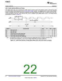
PCM9211
SBAS495 –JUNE 2010
www.ti.com
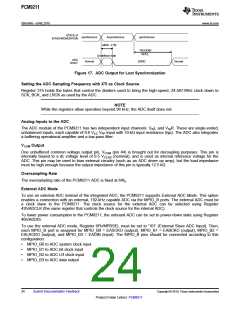
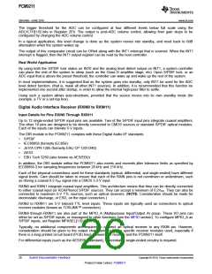
The trigger threshold for the ADC can be configured at four different levels below full scale using the
ADLVLTH[1:0] bits in Register 2Eh. The output is post-ADC volume control, allowing finer gain steps to be
configured by changing the ADC volume control.
In a typical application, this level change is done as the system moves into standby, and reset back to 0dB
attenuation when the system wakes up.
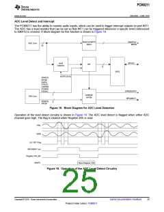
The output of this comparator circuit can be ORed along with the INT1 interrupt that is sourced. When the INT1
interrupt is flagged, then the INT1 output register can be read by the host controller.
Real World Application
By using both the S/PDIF lock status on INT0 and the analog level detect output on INT1, a system controller
can place the rest of the system to sleep (such as the Class D amplifier stage, etc). Upon S/PDIF lock, or an
ADC input that is above the preset threshold, the controller can wake up and wake up the rest of the system.
In most implementations, it is suggested that as the system goes into standby, only INT1 be used for the ADC
level detect function. (that is, mask all other INT1 sources). In addition, it is recommended that this function be
implemented one second after startup, in order to allow the internal high-pass filter to settle.
Using such a system allows auto-shutdown, provided that the source moves into its own standby mode (for
example, a TV or a set-top box).
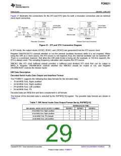
Digital Audio Interface Receiver (RXIN0 to RXIN11)
Input Details for Pins RXIN0 Through RXIN11
Up to 12 single-ended S/PDIF input pins are available. Two of the S/PDIF input pins integrate coaxial amplifiers.
The other 10 pins are designed to be directly connected to CMOS sources or standard S/PDIF optical modules.
Each of the inputs can tolerate 5-V inputs.
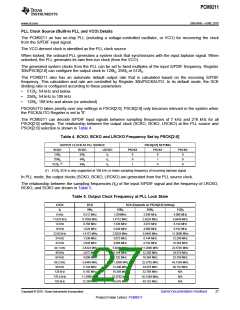
The DIR module in the PCM9211 complies with these Digital Audio I/F standards:
•
•
•
•
•
S/PDIF
IEC60958 (formerly IEC958)
JEITA CPR-1205 (formerly EIAJ CP-1201/340)
AES3
EBU Tech 3250 (also known as AES/EBU)
In addition, the DIR module within the PCM9211 also meets and exceeds jitter tolerance limits as specified by
IEC60958-3 for sampling frequencies between 28 kHz and 216 kHz.
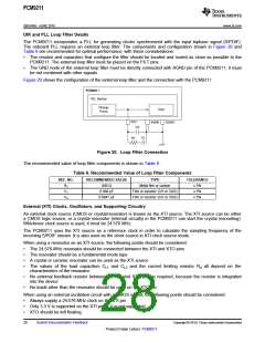
Each of the physical connections used for these standards (optical, differential, and single-ended) have different
signal levels. Care should be taken to ensure that each of the RXIN pins is not overdriven or underdriven, such
as driving a coaxial 0.2-VPP signal into a CMOS 3.3-V input.
RXIN0 and RXIN1 integrate coaxial input amplifiers. This architecture means that they can be directly connected
to either coaxial input (or RCA/Phono) S/PDIF sources. They can accept a minimum of 0.2VPP. They can also be
connected to maximum 5-V TTL sources, such as optical receivers. (NOTE: Consideration should be made for
electrostatic discharge, or ESD, on the input connectors.)
RXIN2 to RXIN11 are 5-V tolerant TTL level inputs. These inputs are typically used as connections to optical
receiver modules (known as TOSLINK™ connectors).
RXIN8 through RXIN11 are also part of the MPIO_A (Multipurpose Input/Output A) group. These I/O pins can
either be set as S/PDIF inputs, or reassigned to other functions (see the MPIO section). To configure MPIO_A as
S/PDIF inputs, set Register MPASEL[1:0] to '00'.
Typically, no additional components are required to connect an optical receiver to any RXIN pin. However,
consideration should be given to the output characteristics of the specific receiver modules used, especially if
there is a long printed circuit board (PCB) trace between the receiver and the PCM9211 itself.
For differential inputs (such as the AES/EBU standard), differential to single-ended circuitry is required.
26
Submit Documentation Feedback
Copyright © 2010, Texas Instruments Incorporated
Product Folder Link(s): PCM9211

 TI [ TEXAS INSTRUMENTS ]