PCM9211
SBAS495 –JUNE 2010
www.ti.com
ADC: Audio Interface Mode and Timing
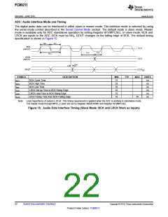
The digital audio data can be interfaced in either slave or master mode. The interface mode is selected by using
the serial mode control described in the Serial Control Mode section. The default mode is slave mode. Master
mode is available only for ADC standalone operation by setting Register 6Fh/MPCSEL. In slave mode, BCK and
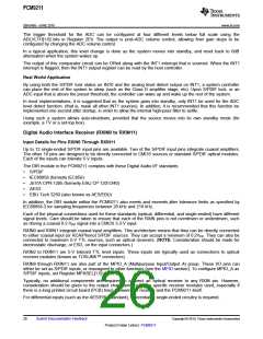
LRCK are inputs to the ADC. BCK must be 64fS. DOUT changes on the falling edge of BCK. The default timing
specification is shown in Figure 15.
tBCH
tBC L
BCK
1.4 V
1.4 V
(INPUT)
tLRH
tLRS
tBC Y
LRCK
(INPUT)
tDOD
DOUT
0.5 V
DD
SYMBOL
tBCY
DESCRIPTION
MIN
75
35
35
10
10
10
TYP
MAX
UNITS
BCK Cycle Time
BCK High Time
BCK Low Time
ns
ns
ns
ns
ns
ns
tBCH
tBCL
tLRS
tLRH
tDOD
LRCK Set-up Time to BCK Rising Edge
LRCK Hold Time to BCK Rising Edge
DOUT Delay Time from BCK Falling Edge
70
Note: Load capacitance of output is 20 pF. This timing requirement is applied when the ADC is working in standalone mode.
The master mode through MPIO_C ports are set by Register 48h/ADIFMD and Register 6Fh/MPCSEL.
Figure 15. Audio Data Interface Timing (Slave Mode: BCK and LRCK Work as Inputs)
22
Submit Documentation Feedback
Copyright © 2010, Texas Instruments Incorporated
Product Folder Link(s): PCM9211

 TI [ TEXAS INSTRUMENTS ]