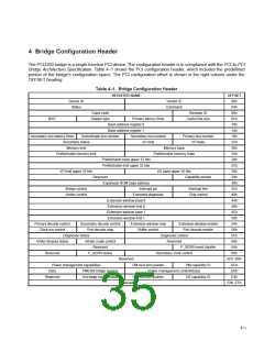
4 Bridge Configuration Header
The PCI2250 bridge is a single-function PCI device. The configuration header is in compliance with the PCI-to-PCI
Bridge Architecture Specification. Table 4–1 shows the PCI configuration header, which includes the predefined
portion of the bridge’s configuration space. The PCI configuration offset is shown in the right column under the
OFFSET heading.
Table 4–1. Bridge Configuration Header
REGISTER NAME
OFFSET
00h
Device ID
Status
Vendor ID
Command
04h
Class code
Header type
Revision ID
08h
BIST
Primary latency timer
Cache line size
0Ch
10h
Base address register 0
Base address register 1
14h
Secondary bus latency timer
Subordinate bus number
Secondary bus number
I/O limit
Primary bus number
I/O base
18h
Secondary status
1Ch
20h
Memory limit
Memory base
Prefetchable memory limit
Prefetchable memory base
24h
Prefetchable base upper 32 bits
Prefetchable limit upper 32 bits
28h
2Ch
30h
I/O limit upper 16 bits
I/O base upper 16 bits
Reserved
Expansion ROM base address
Interrupt pin
Extended diagnostic
Extension window base 0
Capability pointer
34h
38h
Bridge control
Arbiter control
Interrupt line
Chip control
3Ch
40h
44h
Extension window limit 0
Extension window base 1
Extension window limit 1
48h
4Ch
50h
Primary decode control
Clock run control
Secondary decode control
Extension window map
Buffer control
Extension window enable
Port decode enable
54h
Port decode map
58h
Diagnostic status
Diagnostic control
Reserved
P_SERR event disable
Secondary clock control
5Ch
60h
Arbiter timeout status
Arbiter mask control
Reserved
64h
Reserved
P_SERR status
68h
Reserved
PM next item pointer
Power management control/status
HS next item pointer HS capability ID
Reserved
6Ch–D8h
DCh
E0h
E4h
E8h–FFh
Power management capabilities
PM capability ID
Data
PMCSR bridge support
Hot-swap control status
Reserved
4–1

 TI [ TEXAS INSTRUMENTS ]