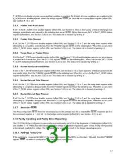
3.10.2 Data Parity Error
If the parity error response bit (bit 6) in the command register (offset 04h, see Section 4.3) is set, then the PCI2250
signalsPERR when it receives bad data. When the bridge detects bad parity, bit 15 (detected parity error) in the status
register (offset 06h, see Section 4.4) is set.
If the bridge is configured to respond to parity errors via bit 6 in the command register, then the data parity error
detected bit (bit 8 in the status register) is set when the bridge detects bad parity. The data parity error detected bit
is also set when the bridge, as a bus master, asserts PERR or detects PERR.
3.11 Master and Target Abort Handling
If the PCI2250 receives a target abort during a write burst, then it signals target abort back on the initiator bus. If it
receives a target abort during a read burst, then it provides all of the valid data on the initiator bus and disconnects.
Target aborts for posted and nonposted transactions are reported as specified in the PCI-to-PCI Bridge Specification.
MasterabortsforpostedandnonpostedtransactionsarereportedasspecifiedinthePCI-to-PCIBridgeSpecification.
If a transaction is attempted on the primary bus after a secondary reset is asserted, then the PCI2250 follows bit 5
(master abort mode bit setting) in the bridge control register (offset 3Eh, see Section 4.32) for reporting errors.
3.12 Discard Timer
The PCI2250 is free to discard the data or status of a delayed transaction that was completed with a delayed
10
15
transaction termination when a bus master has not repeated the request within 2 or 2 PCI clocks (approximately
15
30 µs and 993 µs, respectively). The PCI Local Bus Specification recommends that a bridge wait 2 PCI clocks
before discarding the transaction data or status.
The PCI2250 implements a discard timer for use in delayed transactions. After a delayed transaction is completed
on the destination bus, the bridge may discard it under two conditions. The first condition occurs when a read
transaction is made to a region of memory that that is inside a defined prefetchable memory region, or when the
command is a memory read line or a memory read multiple, implying that the memory region is prefetchable. The
other condition occurs when the master originating the transaction (either a read or a write, prefetchable or
10
15
nonprefetchable) has not retried the transaction within 2 or 2 clocks. The number of clocks is tracked by a timer
referred to as the discard timer. When the discard timer expires, the bridge is required to discard the data. The
15
10
PCI2250 default value for the discard timer is 2 clocks; however, this value can be set to 2 clocks by setting bit 9
in the bridge control register (offset 3Eh, see Section 4.32). For more information on the discard timer, see error
conditions in PCI Local Bus Specification.
3.13 Delayed Transactions
The bridge supports delayed transactions as defined in the PCI Local Bus Specification. A target must be able to
complete the initial data phase in 16 PCI clocks or less from the assertion of the cycle frame (FRAME), and
subsequent data phases must complete in 8 PCI clocks or less. A delayed transaction consists of three phases:
•
•
•
An initiator device issues a request.
The target completes the request on the destination bus and signals the completion to the initiator.
The initiator completes the request on the originating bus.
If the bridge is the target of a PCI transaction and it must access a slow device to write or read the requested data,
and the transaction takes longer than 16 clocks, then the bridge must latch the address, the command, and the byte
enables, and then issue a retry to the initiator. The initiator must end the transaction without any transfer of data and
is required to retry the transaction later using the same address, command, and byte enables. This is the first phase
of the delayed transaction.
During the second phase, if the transaction is a read cycle, then the bridge fetches the requested data on the
destination bus, stores it internally, and obtains the completion status, thus completing the transaction on the
3–8

 TI [ TEXAS INSTRUMENTS ]