Finally, since CS and CF set the high-frequency noise gain,
determine CS using Equation 6 (solving for CS by using NG2 = 24):
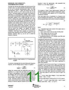
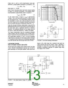
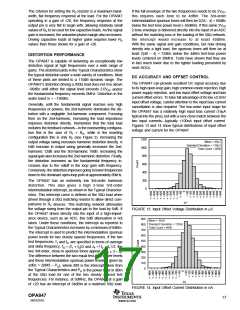
LOW GAIN INVERTING BANDWIDTH
1
0
CS = NG − 1C
(6)
(
)
2
F
G = –8
which gives CS = 40.6pF.
–1
–2
–3
–4
–5
–6
–7
–8
–9
VO = 0.2VPP
Both of these calculated values have been reduced slightly
in Figure 5 to account for parasitics. The resulting closed-
loop bandwidth is approximately equal to Equation 7.
G = –1
G = –2
(7)
f–3dB
ZO • GBP
G = –4
For the values shown in Figure 5, f–3dB is approximately
131MHz. This is less than that predicted by simply dividing
the GBP product by NG1. The compensation network controls
the bandwidth to a lower value, while providing the full slew
rate at the output and an exceptional distortion performance
due to increased loop gain at frequencies below NG1 • ZO.
1
10
100
1000
Frequency (MHz)
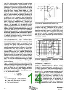
+5V
Using this low-gain inverting compensation, along with the
differential structure for the circuit shown on the front page of
this data sheet, gives a significant reduction in harmonic
distortion. The measured distortion at 2VPP output does not
rise above –95dB until frequencies > 20MHz are applied.
VDIS
VO
OPA847
RF
750Ω
The Typical Characteristics show the exceptional bandwidth
control possible using this technique at low inverting gains.
Figure 6 repeats the measured results with the test circuit shown.
RG
–5V
VI
0Ω Source
CS
CF
The compensation capacitors, CS and CF, are set by targeting
a high-frequency noise gain of 21 and using equations 4 through
6. This approach allows relatively low inverting gain applications
to use the full slew rate and low input noise of the OPA847.
FIGURE 6. Low-Gain Inverting Performance.
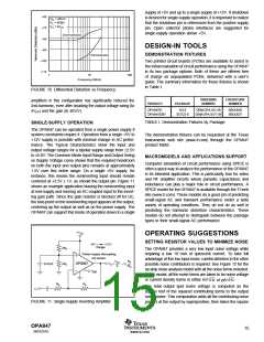
figures in the 10dB range (for a matched 50Ω input) are
easily achieved with just the OPA847, Figure 7 illustrates a
technique to reduce the noise figure even further, while
providing a broadband, high-gain HF amplifier stage using
two stages of the OPA847.
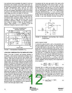
LOW-NOISE FIGURE,
HIGH DYNAMIC RANGE AMPLIFIER
The low input noise voltage of the OPA847 and its very high
2-tone, 3rd-order intermodulation intercept can be used to
good advantage as a fixed-gain amplifier. While input noise
6.19kΩ
+5V
Input match
set by this
feedback path
PO
OPA847
> 55dBm
intercept
to 30MHz
+5V
–5V
50Ω Source
750Ω
1.5kΩ
1:2
PI
OPA847
200Ω
1.6pF
4.3dB
Noise
Figure
–5V
46pF
10pF
420Ω
PO
PI
Overall Gain
= 35.6dB
30.1Ω
FIGURE 7. Very High Dynamic Range HF Amplifier.
OPA847
SBOS251E
13
www.ti.com

 TI [ TEXAS INSTRUMENTS ]