OMAP-L137 Low-Power Applications Processor
SPRS563A–SEPTEMBER 2008–REVISED OCTOBER 2008
www.ti.com
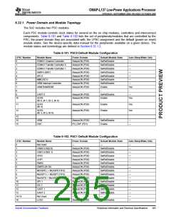
Table 6-102. PSC1 Default Module Configuration (continued)
LPSC Number
Module Name
eHRPWM0/1/2
Not Used
Power Domain
AlwaysON (PD0)
—
Default Module State
SwRstDisable
—
Auto Sleep/Wake Only
17
—
18-19
20
—
ECAP0/1/2
EQEP0/1
AlwaysON (PD0)
AlwaysON (PD0)
—
SwRstDisable
SwRstDisable
—
—
21
—
22-23
24
Not Used
—
SCR8
AlwaysON (PD0)
Enable
Yes
(Br 15)
25
26
SCR7
(Br 12)
AlwaysON (PD0)
AlwaysON (PD0)
Enable
Enable
Yes
Yes
SCR12
(Br 18)
27-30
31
Not Used
—
—
—
Shared RAM
(Br 13)
PD_SHRAM
Enable
Yes
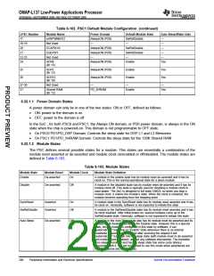
6.32.1.1 Power Domain States
A power domain can only be in one of the two states: ON or OFF, defined as follows:
•
•
ON: power to the domain is on
OFF: power to the domain is off
In the SoC , for both PSC0 and PSC1, the Always ON domain, or PD0 power domain, is always in the ON
state when the chip is powered-on. This domain is not programmable to OFF state.
•
•
On PSC0 PD1/PD_DSP Domain: Controls the sleep state for DSP L1 and L2 Memories
On PSC1 PD1/PD_SHRAM Domain: Controls the sleep state for the 128K Shared RAM
6.32.1.2 Module States
The PSC defines several possible states for a module. This states are essentially a combination of the
module reset asserted or de-asserted and module clock on/enabled or off/disabled. The module states are
defined in Table 6-103.
Table 6-103. Module States
Module State
Module Reset
Module Clock
Module State Definition
Enable
De-asserted
On
A module in the enable state has its module reset de-asserted and it has its
clock on. This is the normal operational state for a given module
Disable
De-asserted
Off
A module in the disabled state has its module reset de-asserted and it has its
module clock off. This state is typically used for disabling a module clock to
save power. The SoC is designed in full static CMOS, so when you stop a
module clock, it retains the module’s state. When the clock is restarted, the
module resumes operating from the stopping point.
SyncReset
Asserted
Asserted
On
Off
A module state in the SyncReset state has its module reset asserted and it has
its clock on. Generally, software is not expected to initiate this state
SwRstDisable
A module in the SwResetDisable state has its module reset asserted and it has
its clock disabled. After initial power-on, several modules come up in the
SwRstDisable state. Generally, software is not expected to initiate this state
Auto Sleep
De-asserted
Off
A module in the Auto Sleep state also has its module reset de-asserted and its
module clock disabled, similar to the Disable state. However this is a special
state, once a module is configured in this state by software, it can
“automatically” transition to “Enable” state whenever there is an internal
read/write request made to it, and after servicing the request it will
“automatically” transition into the sleep state (with module reset re de-asserted
and module clock disabled), without any software intervention. The transition
from sleep to enabled and back to sleep state has some cycle latency
associated with it. It is not envisioned to use this mode when peripherals are
fully operational and moving data.
206
Peripheral Information and Electrical Specifications
Submit Documentation Feedback

 TI [ TEXAS INSTRUMENTS ]