OMAP-L137 Low-Power Applications Processor
www.ti.com
SPRS563A–SEPTEMBER 2008–REVISED OCTOBER 2008
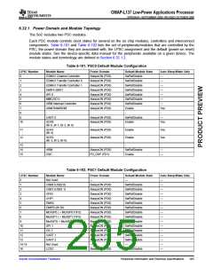
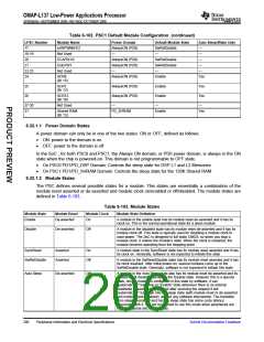
6.32.1 Power Domain and Module Topology
The SoC includes two PSC modules.
Each PSC module controls clock states for several on the on chip modules, controllers and interconnect
components. Table 6-101 and Table 6-102 lists the set of peripherals/modules that are controlled by the
PSC, the power domain they are associated with, the LPSC assignment and the default (power-on reset)
module states. See the device-specific data manual for the peripherals available on a given device. The
module states and terminology are defined in Section 6.32.1.2.
Table 6-101. PSC0 Default Module Configuration
LPSC Number
Module Name
Power Domain
AlwaysON (PD0)
AlwaysON (PD0)
AlwaysON (PD0)
AlwaysON (PD0)
AlwaysON (PD0)
AlwaysON (PD0)
AlwaysON (PD0)
AlwaysON (PD0)
-
Default Module State
SwRstDisable
SwRstDisable
SwRstDisable
SwRstDisable
SwRstDisable
SwRstDisable
SwRstDisable
Enable
Auto Sleep/Wake Only
0
1
2
3
4
5
6
7
8
9
10
EDMA3 Channel Controller
EDMA3 Transfer Controller 0
EDMA3 Transfer Controller 1
EMIFA (BR7)
—
—
—
—
—
—
—
Yes
-
SPI 0
MMC/SD 0
ARM Interrupt Controller
ARM RAM/ROM
-
-
UART 0
AlwaysON (PD0)
AlwaysON (PD0)
SwRstDisable
Enable
—
Yes
SCR0
(Br 0, Br 1, Br 2, Br 8)
11
12
SCR1
(Br 4)
AlwaysON (PD0)
AlwaysON (PD0)
Enable
Enable
Yes
Yes
SCR2
(Br 3, Br 5, Br 6)
13
14
15
-
-
-
-
ARM
DSP
AlwaysON (PD0)
PD_DSP (PD1)
SwRstDisable
Enable
—
—
Table 6-102. PSC1 Default Module Configuration
LPSC Number
Module Name
Not Used
Power Domain
—
Default Module State
—
Auto Sleep/Wake Only
0
—
—
—
—
—
—
—
—
—
—
—
—
—
—
—
—
1
USB0 (USB2.0)
USB1 (USB1.1)
GPIO
AlwaysON (PD0)
AlwaysON (PD0)
AlwaysON (PD0)
AlwaysON (PD0)
AlwaysON (PD0)
AlwaysON (PD0)
AlwaysON (PD0)
AlwaysON (PD0)
AlwaysON (PD0)
AlwaysON (PD0)
AlwaysON (PD0)
AlwaysON (PD0)
AlwaysON (PD0)
—
SwRstDisable
SwRstDisable
SwRstDisable
SwRstDisable
SwRstDisable
SwRstDisable
SwRstDisable
SwRstDisable
SwRstDisable
SwRstDisable
SwRstDisable
SwRstDisable
SwRstDisable
—
2
3
4
UHPI
5
EMAC
6
EMIFB (Br 20)
McASP0 ( + McASP0 FIFO)
McASP1 ( + McASP1 FIFO)
McASP2( + McASP2 FIFO)
SPI 1
7
8
9
10
11
12
13
14-15
16
I2C 1
UART 1
UART 2
Not Used
LCDC
AlwaysON (PD0)
SwRstDisable
Submit Documentation Feedback
Peripheral Information and Electrical Specifications
205

 TI [ TEXAS INSTRUMENTS ]