OMAP-L137 Low-Power Applications Processor
SPRS563A–SEPTEMBER 2008–REVISED OCTOBER 2008
www.ti.com
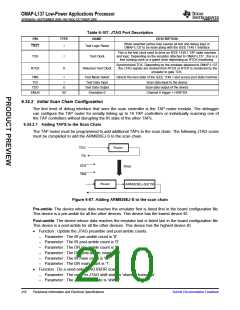
Table 6-107. JTAG Port Description
PIN
TYPE
NAME
DESCRIPTION
When asserted (active low) causes all test and debug logic in
OMAP-L137 to be reset along with the IEEE 1149.1 interface
TRST
I
Test Logic Reset
This is the test clock used to drive an IEEE 1149.1 TAP state machine
and logic. Depending on the emulator attached to OMAP-L137 , this is a
free running clock or a gated clock depending on RTCK monitoring.
TCK
I
Test Clock
Synchronized TCK. Depending on the emulator attached to OMAP-L137
, the JTAG signals are clocked from RTCK or RTCK is monitored by the
emulator to gate TCK.
RTCK
O
Returned Test Clock
TMS
TDI
I
I
Test Mode Select
Test Data Input
Test Data Output
Emulation 0
Directs the next state of the IEEE 1149.1 test access port state machine
Scan data input to the device
TDO
EMU0
O
I/O
Scan data output of the device
Channel 0 trigger + HSRTDX
6.34.2 Initial Scan Chain Configuration
The first level of debug interface that sees the scan controller is the TAP router module. The debugger
can configure the TAP router for serially linking up to 16 TAP controllers or individually scanning one of
the TAP controllers without disrupting the IR state of the other TAPs.
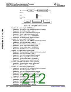
6.34.2.1 Adding TAPS to the Scan Chain
The TAP router must be programmed to add additional TAPs to the scan chain. The following JTAG scans
must be completed to add the ARM926EJ-S to the scan chain.
TDO
TDI
Router
CLK
TMS
Steps
Router
ARM926EJ-S/ETM
Figure 6-67. Adding ARM926EJ-S to the scan chain
Pre-amble: The device whose data reaches the emulator first is listed first in the board configuration file.
This device is a pre-amble for all the other devices. This device has the lowest device ID.
Post-amble: The device whose data reaches the emulator last is listed last in the board configuration file.
This device is a post-amble for all the other devices. This device has the highest device ID.
•
Function : Update the JTAG preamble and post-amble counts.
–
–
–
–
–
–
Parameter : The IR pre-amble count is '0'.
Parameter : The IR post-amble count is '0'.
Parameter : The DR pre-amble count is '0'.
Parameter : The DR post-amble count is '0'.
Parameter : The IR main count is '6'.
Parameter : The DR main count is '1'.
•
Function : Do a send-only JTAG IR/DR scan.
–
–
Parameter : The route to JTAG shift state is 'shortest transition'.
Parameter : The JTAG shift state is 'shift-ir'.
210
Peripheral Information and Electrical Specifications
Submit Documentation Feedback

 TI [ TEXAS INSTRUMENTS ]