MSP430F530x, MSP430F5310
SLAS677B –SEPTEMBER 2010–REVISED MARCH 2011
www.ti.com
MAX UNIT
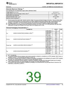
Recommended Operating Conditions
MIN NOM
PMMCOREVx = 0
1.8
2.0
2.2
2.4
0
3.6
3.6
3.6
3.6
V
V
PMMCOREVx = 0, 1
PMMCOREVx = 0, 1, 2
PMMCOREVx = 0, 1, 2, 3
Supply voltage during program execution and flash
VCC
(1)
programming(AVCC = DVCC1/2 = DVCC
)
V
V
VSS
TA
Supply voltage (AVSS = DVSS1/2 = DVSS
Operating free-air temperature
Operating junction temperature
Capacitor at VCORE
)
V
I version
I version
–40
-40
470
85
85
°C
°C
nF
TJ
CVCORE
CDVCC
CVCORE
/
Capacitor ratio of DVCC to VCORE
10
PMMCOREVx = 0,
1.8 V ≤ VCC ≤ 3.6 V
(default condition)
0
8.0
PMMCOREVx = 1,
2.0 V ≤ VCC ≤ 3.6 V
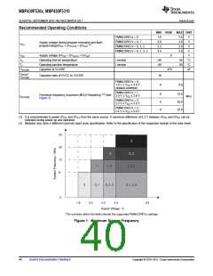
Processor frequency (maximum MCLK frequency) (2) (see
Figure 1)
0
0
0
12.0
20.0
25.0
fSYSTEM
MHz
PMMCOREVx = 2,
2.2 V ≤ VCC ≤ 3.6 V
PMMCOREVx = 3,
2.4 V ≤ VCC ≤ 3.6 V
(1) It is recommended to power AVCC and DVCC from the same source. A maximum difference of 0.3 V between AVCC and DVCC can be
tolerated during power up and operation.
(2) Modules may have a different maximum input clock specification. Refer to the specification of the respective module in this data sheet.
25
3
20
2, 3
2
12
8
1, 2
1, 2, 3
1
0
0, 1
0, 1, 2
0, 1, 2, 3
0
1.8
2.0
2.2
2.4
3.6
Supply Voltage - V
The numbers within the fields denote the supported PMMCOREVx settings.
Figure 1. Maximum System Frequency
40
Submit Documentation Feedback
Copyright © 2010–2011, Texas Instruments Incorporated

 TI [ TEXAS INSTRUMENTS ]