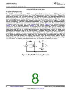
LM3410, LM3410Q
SNVS541G –OCTOBER 2007–REVISED MAY 2013
www.ti.com
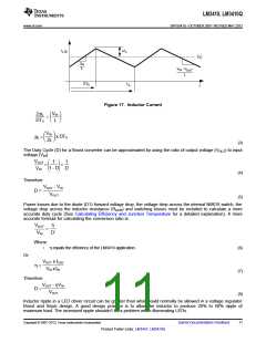
From the previous equations, the inductor value is then obtained.
V
2DiL
≈
’
IN
x DT
∆
∆
÷
÷
L =
S
«
◊
(9)
Where
1/TS = fSW
(10)
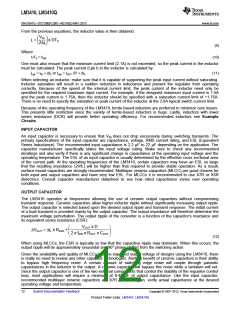
One must also ensure that the minimum current limit (2.1A) is not exceeded, so the peak current in the inductor
must be calculated. The peak current (Lpk I) in the inductor is calculated by:
ILpk = IIN + ΔIL or ILpk = IOUT /D' + ΔiL
(11)
When selecting an inductor, make sure that it is capable of supporting the peak input current without saturating.
Inductor saturation will result in a sudden reduction in inductance and prevent the regulator from operating
correctly. Because of the speed of the internal current limit, the peak current of the inductor need only be
specified for the required maximum input current. For example, if the designed maximum input current is 1.5A
and the peak current is 1.75A, then the inductor should be specified with a saturation current limit of >1.75A.
There is no need to specify the saturation or peak current of the inductor at the 2.8A typical switch current limit.
Because of the operating frequency of the LM3410, ferrite based inductors are preferred to minimize core losses.
This presents little restriction since the variety of ferrite-based inductors is huge. Lastly, inductors with lower
series resistance (DCR) will provide better operating efficiency. For recommended inductors see Example
Circuits.
INPUT CAPACITOR
An input capacitor is necessary to ensure that VIN does not drop excessively during switching transients. The
primary specifications of the input capacitor are capacitance, voltage, RMS current rating, and ESL (Equivalent
Series Inductance). The recommended input capacitance is 2.2 µF to 22 µF depending on the application. The
capacitor manufacturer specifically states the input voltage rating. Make sure to check any recommended
deratings and also verify if there is any significant change in capacitance at the operating input voltage and the
operating temperature. The ESL of an input capacitor is usually determined by the effective cross sectional area
of the current path. At the operating frequencies of the LM3410, certain capacitors may have an ESL so large
that the resulting impedance (2πfL) will be higher than that required to provide stable operation. As a result,
surface mount capacitors are strongly recommended. Multilayer ceramic capacitors (MLCC) are good choices for
both input and output capacitors and have very low ESL. For MLCCs it is recommended to use X7R or X5R
dielectrics. Consult capacitor manufacturer datasheet to see how rated capacitance varies over operating
conditions.
OUTPUT CAPACITOR
The LM3410 operates at frequencies allowing the use of ceramic output capacitors without compromising
transient response. Ceramic capacitors allow higher inductor ripple without significantly increasing output ripple.
The output capacitor is selected based upon the desired output ripple and transient response. The initial current
of a load transient is provided mainly by the output capacitor. The output impedance will therefore determine the
maximum voltage perturbation. The output ripple of the converter is a function of the capacitor’s reactance and
its equivalent series resistance (ESR):
VOUT x D
≈
∆
«
’
÷
◊
DVOUT = DiL x RESR
+
2 x fSW x ROUT x COUT
(12)
When using MLCCs, the ESR is typically so low that the capacitive ripple may dominate. When this occurs, the
output ripple will be approximately sinusoidal and 90° phase shifted from the switching action.
Given the availability and quality of MLCCs and the expected output voltage of designs using the LM3410, there
is really no need to review any other capacitor technologies. Another benefit of ceramic capacitors is their ability
to bypass high frequency noise. A certain amount of switching edge noise will couple through parasitic
capacitances in the inductor to the output. A ceramic capacitor will bypass this noise while a tantalum will not.
Since the output capacitor is one of the two external components that control the stability of the regulator control
loop, most applications will require a minimum at 0.47 µF of output capacitance. Like the input capacitor,
recommended multilayer ceramic capacitors are X7R or X5R. Again, verify actual capacitance at the desired
operating voltage and temperature.
12
Submit Documentation Feedback
Copyright © 2007–2013, Texas Instruments Incorporated
Product Folder Links: LM3410 LM3410Q

 TI [ TEXAS INSTRUMENTS ]