LM3410, LM3410Q
SNVS541G –OCTOBER 2007–REVISED MAY 2013
Design Guide
www.ti.com
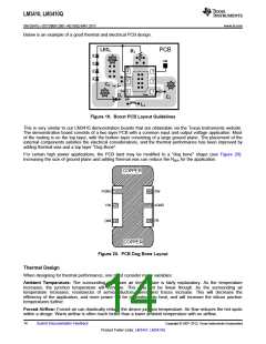
SETTING THE LED CURRENT
I
LED
V
FB
RSET
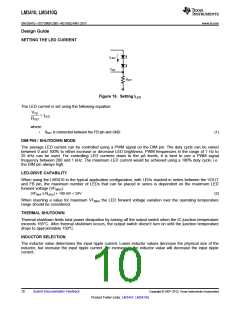
Figure 16. Setting ILED
The LED current is set using the following equation:
VFB
= ILED
RSET
where
•
RSET is connected between the FB pin and GND.
(1)
DIM PIN / SHUTDOWN MODE
The average LED current can be controlled using a PWM signal on the DIM pin. The duty cycle can be varied
between 0 and 100% to either increase or decrease LED brightness. PWM frequencies in the range of 1 Hz to
25 kHz can be used. For controlling LED currents down to the µA levels, it is best to use a PWM signal
frequency between 200 and 1 kHz. The maximum LED current would be achieved using a 100% duty cycle, i.e.
the DIM pin always high.
LED-DRIVE CAPABILITY
When using the LM3410 in the typical application configuration, with LEDs stacked in series between the VOUT
and FB pin, the maximum number of LEDs that can be placed in series is dependent on the maximum LED
forward voltage (VFMAX).
(VFMAX x NLEDs) + 190 mV < 24V
(2)
When inserting a value for maximum VFMAX the LED forward voltage variation over the operating temperature
range should be considered.
THERMAL SHUTDOWN
Thermal shutdown limits total power dissipation by turning off the output switch when the IC junction temperature
exceeds 165°C. After thermal shutdown occurs, the output switch doesn’t turn on until the junction temperature
drops to approximately 150°C.
INDUCTOR SELECTION
The inductor value determines the input ripple current. Lower inductor values decrease the physical size of the
inductor, but increase the input ripple current. An increase in the inductor value will decrease the input ripple
current.
10
Submit Documentation Feedback
Copyright © 2007–2013, Texas Instruments Incorporated
Product Folder Links: LM3410 LM3410Q

 TI [ TEXAS INSTRUMENTS ]