LM3410, LM3410Q
www.ti.com
SNVS541G –OCTOBER 2007–REVISED MAY 2013
VOUT + VD
V
( )
sw t
t
V
IN
V
( )
L t
t
V
-V
-V
OUT D
IN
I
i
( )
L t
L
t
I
( )
DIODE t
t
i
- i
-
OUT
(
L
)
I
( )
t
Capacitor
t
- i
OUT
Dv
V
( )
t
OUT
DT
T
S
S
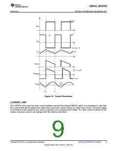
Figure 15. Typical Waveforms
CURRENT LIMIT
The LM3410 uses cycle-by-cycle current limiting to protect the internal NMOS switch. It is important to note that
this current limit will not protect the output from excessive current during an output short circuit. The input supply
is connected to the output by the series connection of an inductor and a diode. If a short circuit is placed on the
output, excessive current can damage both the inductor and diode.
Copyright © 2007–2013, Texas Instruments Incorporated
Submit Documentation Feedback
9
Product Folder Links: LM3410 LM3410Q

 TI [ TEXAS INSTRUMENTS ]