LM3410, LM3410Q
SNVS541G –OCTOBER 2007–REVISED MAY 2013
www.ti.com
Thermal Definitions
Heat energy is transferred from regions of high temperature to regions of low temperature via three basic
mechanisms: radiation, conduction and convection.
Radiation: Electromagnetic transfer of heat between masses at different temperatures.
Conduction: Transfer of heat through a solid medium.
Convection: Transfer of heat through the medium of a fluid; typically air.
Conduction and Convection will be the dominant heat transfer mechanism in most applications.
R
R
C
C
R
θJA: Thermal impedance from silicon junction to ambient air temperature.
θJC: Thermal impedance from silicon junction to device case temperature.
θJC: Thermal Delay from silicon junction to device case temperature.
θCA: Thermal Delay from device case to ambient air temperature.
θJA and RθJC: These two symbols represent thermal impedances, and most data sheets contain associated
values for these two symbols. The units of measurement are °C/Watt.
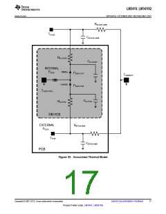
RθJA is the sum of smaller thermal impedances (see simplified thermal model Figure 21 and Figure 22).
Capacitors within the model represent delays that are present from the time that power and its associated
heat is increased or decreased from steady state in one medium until the time that the heat increase or
decrease reaches steady state in the another medium.
The datasheet values for these symbols are given so that one might compare the thermal performance of one
package against another. To achieve a comparison between packages, all other variables must be held constant
in the comparison (PCB size, copper weight, thermal vias, power dissipation, VIN, VOUT, load current etc). This
does shed light on the package performance, but it would be a mistake to use these values to calculate the
actual junction temperature in your application.
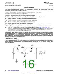
LM3410 Thermal Models
Heat is dissipated from the LM3410 and other devices. The external loss elements include the Schottky diode,
inductor, and loads. All loss elements will mutually increase the heat on the PCB, and therefore increase each
other’s temperatures.
L
1
I
D
1
L(t)
V
OUT(t)
V
Q
1
IN
C
1
Figure 21. Thermal Schematic
16
Submit Documentation Feedback
Copyright © 2007–2013, Texas Instruments Incorporated
Product Folder Links: LM3410 LM3410Q

 TI [ TEXAS INSTRUMENTS ]