LM26420, LM26420-Q0, LM26420-Q1
SNVS579J –FEBRUARY 2009–REVISED SEPTEMBER 2015
www.ti.com
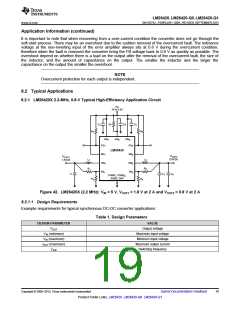
8.2.1.2 Detailed Design Procedure
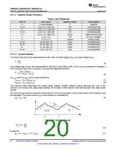
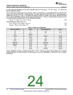
Table 2. Bill Of Materials
PART ID
U1
PART VALUE
MANUFACTURER
PART NUMBER
2 A Buck Regulator
15 µF, 6.3 V, 1206, X5R
33 µF, 6.3 V, 1206, X5R
22 µF, 6.3 V, 1206, X5R
0.47 µF, 10 V, 0805, X7R
1.0 µH, 7.9 A
TI
LM26420X
C3216X5R0J156M
C3216X5R0J336M
C3216X5R0J226M
VJ0805Y474KXQCW1BC
RLF7030T-1R0M6R4
LPS4414-701ML
C3, C4
C1
TDK
TDK
C2, C6
C5
TDK
Vishay
TDK
L1
L2
0.7 µH, 3.7 A
Coilcraft
Vishay
Vishay
Vishay
Vishay
R3, R4
R5, R6
R1
10.0 kΩ, 0603, 1%
49.9 kΩ, 0603, 1%
12.7 kΩ, 0603, 1%
4.99 Ω, 0603, 1%
CRCW060310K0F
CRCW060649K9F
CRCW060312K7F
CRCW06034R99F
R7, R2
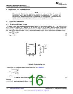
8.2.1.2.1 Inductor Selection
The Duty Cycle (D) can be approximated as the ratio of output voltage (VOUT) to input voltage (VIN):
VOUT
D =
VIN
(5)
The voltage drop across the internal NMOS (SW_BOT) and PMOS (SW_TOP) must be included to calculate a
more accurate duty cycle. Calculate D by using the following formulas:
VOUT + VSW_BOT
D =
VIN + VSW_BOT ± VSW_TOP
(6)
VSW_TOP and VSW_BOT can be approximated by:
VSW_TOP = IOUT x RDSON_TOP
VSW_BOT = IOUT x RDSON_BOT
(7)
(8)
The inductor value determines the output ripple voltage. Smaller inductor values decrease the size of the
inductor, but increase the output ripple voltage. An increase in the inductor value will decrease the output ripple
current.
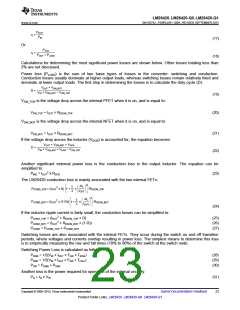
One must ensure that the minimum current limit (2.4 A) is not exceeded, so the peak current in the inductor must
be calculated. The peak current (ILPK) in the inductor is calculated by:
ILPK = IOUT + ΔiL
(9)
'i
L
I
OUT
V
OUT
V
- V
OUT
IN
L
L
t
DT
T
S
S
Figure 43. Inductor Current
VIN - VOUT
L
2'iL
=
DTS
(10)
(11)
In general,
ΔiL = 0.1 × (IOUT) → 0.2 × (IOUT
)
20
Submit Documentation Feedback
Copyright © 2009–2015, Texas Instruments Incorporated
Product Folder Links: LM26420 LM26420-Q0 LM26420-Q1

 TI [ TEXAS INSTRUMENTS ]