LM26420, LM26420-Q0, LM26420-Q1
SNVS579J –FEBRUARY 2009–REVISED SEPTEMBER 2015
www.ti.com
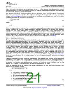
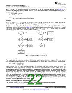
Iav= I1 × D1 + I2 × D2. To quickly determine the values of d1, d2 and d3, refer to the decision tree in Figure 44. To
determine the duty cycle of each channel, use D = VOUT/VIN for a quick result or use the following equation for a
more accurate result.
VOUT + VSW_BOT + IOUT x RDC
D =
VIN + VSW_BOT - VSW_TOP
where
•
RDC is the winding resistance of the inductor.
(15)
Example:
VIN = 5 V, VOUT1 = 3.3 V, IOUT1 = 2 A, VOUT2 = 1.2 V, IOUT2 = 1.5 A, RDS = 170 mΩ, RDC = 30 mΩ. (IOUT1 is the
same as I1 in the input ripple RMS current equation, IOUT2 is the same as I2).
First, find out the duty cycles. Plug the numbers into the duty cycle equation and we get D1 = 0.75, and D2 =
0.33. Next, follow the decision tree in Figure 44 to find out the values of d1, d2 and d3. In this case, d1 = 0.5, d2
= D2 + 0.5 – D1 = 0.08, and d3 = D1 – 0.5 = 0.25. Iav = IOUT1 × D1 + IOUT2 x D2 = 1.995 A. Plug all the numbers
into the input ripple RMS current equation and the result is IIR(rms) = 0.77 A.
Figure 44. Determining D1, D2, And D3
8.2.1.2.3 Output Capacitor
The output capacitor is selected based upon the desired output ripple and transient response. The initial current
of a load transient is provided mainly by the output capacitor. The output ripple of the converter is approximately:
1
RESR
+
'VOUT = 'IL
8 x FSW x COUT
(16)
When using MLCCs, the ESR is typically so low that the capacitive ripple may dominate. When this occurs, the
output ripple will be approximately sinusoidal and 90° phase shifted from the switching action. Given the
availability and quality of MLCCs and the expected output voltage of designs using the LM26420, there is really
no need to review any other capacitor technologies. Another benefit of ceramic capacitors is their ability to
bypass high frequency noise. A certain amount of switching edge noise will couple through parasitic
capacitances in the inductor to the output. A ceramic capacitor will bypass this noise while a tantalum will not.
Since the output capacitor is one of the two external components that control the stability of the regulator control
loop, most applications will require a minimum of 22 µF of output capacitance. Capacitance often, but not always,
can be increased significantly with little detriment to the regulator stability. Like the input capacitor, recommended
multilayer ceramic capacitors are X7R or X5R types.
8.2.1.2.4 Calculating Efficiency, and Junction Temperature
The complete LM26420 DC-DC converter efficiency can be estimated in the following manner.
22
Submit Documentation Feedback
Copyright © 2009–2015, Texas Instruments Incorporated
Product Folder Links: LM26420 LM26420-Q0 LM26420-Q1

 TI [ TEXAS INSTRUMENTS ]