LM26420, LM26420-Q0, LM26420-Q1
www.ti.com
SNVS579J –FEBRUARY 2009–REVISED SEPTEMBER 2015
Application Information (continued)
1
0.8V
2.5V
3.5% ꢀ 1.5%
1 ꢀ
V =
= 1.4%
1 + 2x
(4)
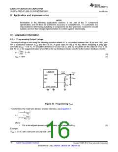
Choose 1% resistors. If R2 = 10 kΩ, then R1 is 21.25 kΩ.
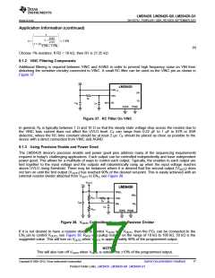
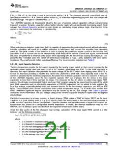
8.1.2 VINC Filtering Components
Additional filtering is required between VINC and AGND in order to prevent high frequency noise on VIN from
disturbing the sensitive circuitry connected to VINC. A small RC filter can be used on the VINC pin as shown in
Figure 37.
V
IN
LM26420
VIND
VINC
1,2
SW
FB
R
F
EN
C
IN
C
F
AGND
PGND
Figure 37. RC Filter On VINC
In general, RF is typically between 1 Ω and 10 Ω so that the steady state voltage drop across the resistor due to
the VINC bias current does not affect the UVLO level. CF can range from 0.22 µF to 1 µF in X7R or X5R
dielectric, where the RC time constant should be at least 2 µs. CF should be placed as close as possible to the
device with a direct connection from VINC and AGND.
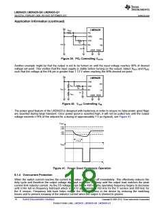
8.1.3 Using Precision Enable and Power Good
The LM26420 device's precision enable and power good pins address many of the sequencing requirements
required in today's challenging applications. Each output can be controlled independently and have independent
power good. This allows for a multitude of ways to control each output. Typically, the enables to each output are
tied together to the input voltage and the outputs will ratiometrically ramp up when the input voltage reaches
above UVLO rising threshold. There may be instances where it is desired that the second output (VOUT2) does
not turn on until the first output (VOUT1) has reached 90% of the desired set-point. This is easily achieved with an
external resistor divider attached from VOUT1 to EN2, see Figure 38.
Figure 38. VOUT1 Controlling VOUT2 with Resistor Divider
If it is not desired to have a resistor divider to control VOUT2 with VOUT1, then the PG1 can be connected to the
EN2 pin to control VOUT2, see Figure 39. RPG1 is a pullup resistor on the range of 10 kΩ to 100 kΩ, 50 kΩ is the
suggested value. This will turn on VOUT2 when VOUT1 is approximately 90% of the programmed output.
NOTE
This will also turn off VOUT2 when VOUT1 is outside the ±10% of the programmed output.
Copyright © 2009–2015, Texas Instruments Incorporated
Submit Documentation Feedback
17
Product Folder Links: LM26420 LM26420-Q0 LM26420-Q1

 TI [ TEXAS INSTRUMENTS ]