LM26420, LM26420-Q0, LM26420-Q1
www.ti.com
SNVS579J –FEBRUARY 2009–REVISED SEPTEMBER 2015
If ΔiL = 20% of 2 A, the peak current in the inductor will be 2.4 A. The minimum ensured current limit over all
operating conditions is 2.4 A. One can either reduce ΔiL, or make the engineering judgment that zero margin will
be safe enough. The typical current limit is 3.3 A.
The LM26420 operates at frequencies allowing the use of ceramic output capacitors without compromising
transient response. Ceramic capacitors allow higher inductor ripple without significantly increasing output ripple
voltage. See Output Capacitor section for more details on calculating output voltage ripple. Now that the ripple
current is determined, the inductance is calculated by:
DTS
2'iL
x (VIN - VOUT
)
L =
(12)
Where
1
fS
TS =
(13)
When selecting an inductor, make sure that it is capable of supporting the peak output current without saturating.
Inductor saturation will result in a sudden reduction in inductance and prevent the regulator from operating
correctly. The peak current of the inductor is used to specify the maximum output current of the inductor and
saturation is not a concern due to the exceptionally small delay of the internal current limit signal. Ferrite based
inductors are preferred to minimize core losses when operating with the frequencies used by the LM26420. This
presents little restriction since the variety of ferrite-based inductors is huge. Lastly, inductors with lower series
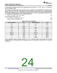
resistance (RDCR) will provide better operating efficiency. For recommended inductors see Table 2.
8.2.1.2.2 Input Capacitor Selection
The input capacitors provide the AC current needed by the nearby power switch so that current provided by the
upstream power supply does not carry a lot of AC content, generating less EMI. To the buck regulator in
question, the input capacitor also prevents the drain voltage of the FET switch from dipping when the FET is
turned on, therefore providing a healthy line rail for the LM26420 to work with. Since typically most of the AC
current is provided by the local input capacitors, the power loss in those capacitors can be a concern. In the case
of the LM26420 regulator, since the two channels operate 180° out of phase, the AC stress in the input
capacitors is less than if they operated in phase. The measure for the AC stress is called input ripple RMS
current. It is strongly recommended that at least one 10µF ceramic capacitor be placed next to each of the VIND
pins. Bulk capacitors such as electrolytic capacitors or OSCON capacitors can be added to help stabilize the
local line voltage, especially during large load transient events. As for the ceramic capacitors, use X7R or X5R
types. They maintain most of their capacitance over a wide temperature range. Try to avoid sizes smaller than
0805. Otherwise significant drop in capacitance may be caused by the DC bias voltage. See Output Capacitor
section for more information. The DC voltage rating of the ceramic capacitor should be higher than the highest
input voltage.
Capacitor temperature is a major concern in board designs. While using a 10-µF or higher MLCC as the input
capacitor is a good starting point, it is a good idea to check the temperature in the real thermal environment to
make sure the capacitors are not over-heated. Capacitor vendors may provide curves of ripple RMS current vs.
temperature rise, based on a designated thermal impedance. In reality, the thermal impedance may be very
different. So it is always a good idea to check the capacitor temperature on the board.
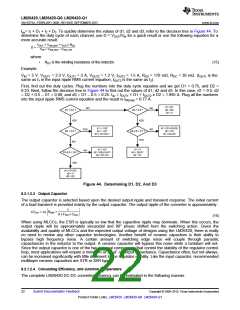
Since the duty cycles of the two channels may overlap, calculation of the input ripple RMS current is a little
tedious. Use the following equation.
I
=
(I1- Iav)2d1+(I2 - Iav)2 d2 +(I1+I2 - Iav)2 d3
irrms
where
•
•
•
•
•
•
I1 is Channel 1's maximum output current.
I2 is Channel 2's maximum output current.
d1 is the non-overlapping portion of Channel 1's duty cycle D1.
d2 is the non-overlapping portion of Channel 2's duty cycle D2.
d3 is the overlapping portion of the two duty cycles.
Iav is the average input current.
(14)
21
Copyright © 2009–2015, Texas Instruments Incorporated
Submit Documentation Feedback
Product Folder Links: LM26420 LM26420-Q0 LM26420-Q1

 TI [ TEXAS INSTRUMENTS ]