LM26420, LM26420-Q0, LM26420-Q1
SNVS579J –FEBRUARY 2009–REVISED SEPTEMBER 2015
www.ti.com
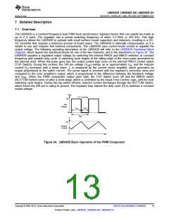
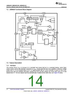
7.2 LM26420 Functional Block Diagram
VIN
EN
OVP
I
LIMIT
SHDN
ENABLE and
UVLO
Thermal
SHDN
x
+
-
VREF 1.15
+
-
I
SENSE
-
+
Control
Logic
RAMP
Artificial
Clock
2.2 MHz/550 kHz
I
SENSE
S
R
R
Q
ꢀ
P-FET
N-FET
ꢀ
Dead-
Time-
Control
Logic
+
-
DRIVERS
SW
FB
-
+
Internal-
Comp
Q
R
V
=0.8 V
REF
+
-
S
Internal - LDO
SOFT-START
I
REVERSE-LIMIT
Pgood
880 mV
720 mV
+
-
+
-
GND
7.3 Feature Description
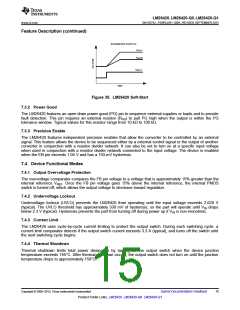
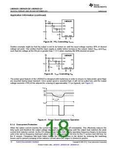
7.3.1 Soft-Start
This function forces VOUT to increase at a controlled rate during start-up in a controlled fashion, which helps
reduce inrush current and eliminate overshoot on VOUT. During soft-start, the error amplifier’s reference voltage
ramps from 0 V to its nominal value of 0.8 V in approximately 600 µs. If the converter is turned on into a pre-
biased load, then the feedback will begin ramping from the pre-bias voltage but at the same rate as if it had
started from 0 V. The two outputs start up ratiometrically if enabled at the same time, see Figure 35 below.
14
Submit Documentation Feedback
Copyright © 2009–2015, Texas Instruments Incorporated
Product Folder Links: LM26420 LM26420-Q0 LM26420-Q1

 TI [ TEXAS INSTRUMENTS ]