DRV8874
SLVSF66A –AUGUST 2019–REVISED DECEMBER 2019
www.ti.com
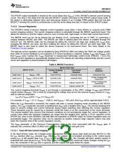
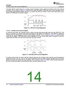
The fixed off-time mode allows for a simple current chopping scheme without involvement from the external
controller. This is shown in Figure 12. Fixed off-time mode will support 100% duty cycle current regulation since
the H-bridge automatically enables after the tOFF period and does not require a new control input edge on the
EN/IN1 or PH/IN2 pins to reset the outputs.
ITRIP
IOUT
VOUT
Control
Input
tOFF
tOFF
tOFF
Figure 12. Off-Time Current-Regulation
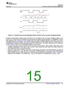
7.3.3.2.2 Cycle-By-Cycle Current Chopping
In cycle-by-cycle mode, the H-bridge enters a brake, low-side slow decay state (both low-side MOSFETs ON)
after IOUT exceeds ITRIP until the next control input edge on the EN/IN1 or PH/IN2 pins. This allows for additional
control of the current chopping scheme by the external controller. This is shown in Figure 13. Cycle-by-cycle
mode will not support 100% duty cycle current regulation as a new control input edge is required to reset the
outputs after the brake, low-side slow decay state has been entered.
ITRIP
IOUT
VOUT
Control
Input
Re-enable
Re-enable
Figure 13. Cycle-By-Cycle Current Regulation
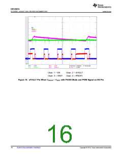
In cycle-by-cycle mode, the device will also indicate whenever the H-bridge enters internal current chopping by
pulling the nFAULT pin low. This can be used to determine when the device outputs will differ from the control
inputs or the load has reached the ITRIP threshold. This is shown in Figure 14. nFAULT will be released whenever
the next control input edge is received by the device and the outputs are reset.
14
Submit Documentation Feedback
Copyright © 2019, Texas Instruments Incorporated

 TI [ TEXAS INSTRUMENTS ]