DRV8874
www.ti.com
SLVSF66A –AUGUST 2019–REVISED DECEMBER 2019
7.3.4 Protection Circuits
The DRV887x family of devices are fully protected against supply undervoltage, charge pump undervoltage,
output overcurrent, and device overtemperature events.
7.3.4.1 VM Supply Undervoltage Lockout (UVLO)
If at any time the supply voltage on the VM pin falls below the undervoltage lockout threshold voltage (VUVLO), all
MOSFETs in the H-bridge will be disabled and the nFAULT pin driven low. The charge pump is disabled in this
condition. Normal operation will resume when the undervoltage condition is removed and VM rises above the
VUVLO threshold.
7.3.4.2 VCP Charge Pump Undervoltage Lockout (CPUV)
If at any time the charge pump voltage on the VCP pin falls below the undervoltage lockout threshold voltage
(VCPUV), all MOSFETs in the H-bridge will be disabled and the nFAULT pin driven low. Normal operation will
resume when the undervoltage condition is removed and VCP rises above the VCPUV threshold.
7.3.4.3 OUTx Overcurrent Protection (OCP)
An analog current limit circuit on each MOSFET limits the peak current out of the device even in hard short
circuit events.
If the output current exceeds the overcurrent threshold, IOCP, for longer than tOCP, all MOSFETs in the H-bridge
will be disabled and the nFAULT pin driven low. The overcurrent response can be configured through the IMODE
pin as shown in Table 6.
In automatic retry mode, the MOSFETs will be disabled and nFAULT pin driven low for a duration of tRETRY. After
tRETRY, the MOSFETs are re-enabled according to the state of the EN/IN1 and PH/IN2 pins. If the overcurrent
condition is still present, the cycle repeats; otherwise normal device operation resumes.
In latched off mode, the MOSFETs will remain disabled and nFAULT pin driven low until the device is reset
through either the nSLEEP pin or by removing the VM power supply.
In Independent Half-Bridge Control Mode (PMODE = Hi-Z), the OCP behavior is slightly modified. If an
overcurrent event is detected, only the corresponding half-bridge will be disabled and the nFAULT pin driven low.
The other half-bridge will continue normal operation. This allows for the device to manage independent fault
events when driving independent loads. If an overcurrent event is detected in both half-bridges, both half-bridges
will be disabled and the nFAULT pin driven low. In automatic retry mode, both half-bridges share the same
overcurrent retry timer. If an overcurrent event occurs first in one half-bridge and then later in the secondary half-
bridge, but before tRETRY has expired, the retry timer for the first half-bridge will be reset to tRETRY and both half-
bridges will enable again after the retry timer expires.
7.3.4.4 Thermal Shutdown (TSD)
If the die temperature exceeds the overtemperature limit TTSD, all MOSFET in the H-bridge will be disabled and
the nFAULT pin driven low. Normal operation will resume when the overtemperature condition is removed and
the die temperature drops below the TTSD threshold.
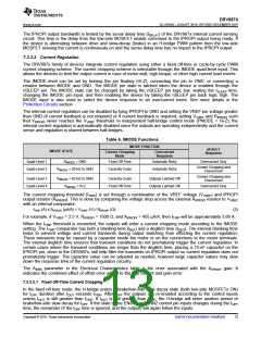
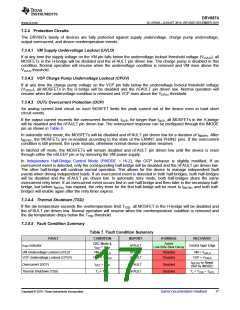
7.3.4.5 Fault Condition Summary
Table 7. Fault Condition Summary
FAULT
CONDITION
REPORT
H-BRIDGE
RECOVERY
CBC Mode &
IOUT > ITRIP
Active
Low-Side Slow Decay
ITRIP Indicator
nFAULT
Control Input Edge
VM Undervoltage Lockout (UVLO)
VCP Undervoltage Lockout (CPUV)
VM < VUVLO
nFAULT
nFAULT
Disabled
Disabled
VM > VUVLO
VCP < VCPUV
VCP > VCPUV
tRETRY or Reset
(Set by IMODE)
Overcurrent (OCP)
IOUT > IOCP
TJ > TTSD
nFAULT
nFAULT
Disabled
Disabled
Thermal Shutdown (TSD)
TJ < TTSD – THYS
Copyright © 2019, Texas Instruments Incorporated
Submit Documentation Feedback
17

 TI [ TEXAS INSTRUMENTS ]