DRV8874
www.ti.com
SLVSF66A –AUGUST 2019–REVISED DECEMBER 2019
The IPROPI output bandwidth is limited by the sense delay time (tDELAY) of the DRV887x internal current sensing
circuit. This time is the delay from the low-side MOSFET enable command to the IPROPI output being ready. If
the device is alternating between drive and slow-decay (brake) in an H-bridge PWM pattern then the low-side
MOSFET sensing the current is continuously on and the sense delay time has no impact to the IPROPI output.
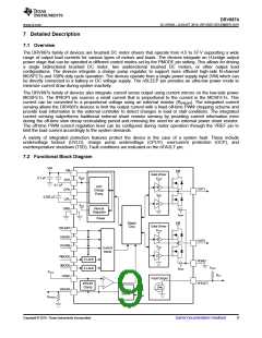
7.3.3.2 Current Regulation
The DRV887x family of devices integrate current regulation using either a fixed off-time or cycle-by-cycle PWM
current chopping scheme. The current chopping scheme is selectable through the IMODE quad-level input. This
allows the devices to limit the output current in case of motor stall, high torque, or other high current load events.
The IMODE level can be set by leaving the pin floating (Hi-Z), connecting the pin to GND, or connecting a
resistor between IMODE and GND. The IMODE pin state is latched when the device is enabled through the
nSLEEP pin. The IMODE state can be changed by taking the nSLEEP pin logic low, waiting the tSLEEP time,
changing the IMODE pin input, and then enabling the device by taking the nSLEEP pin back logic high. The
IMODE input is also used to select the device response to an overcurrent event. See more details in the
Protection Circuits section.
The internal current regulation can be disabled by tying IPROPI to GND and setting the VREF pin voltage greater
than GND (if current feedback is not required) or if current feedback is required, setting VVREF and RIPROPI such
that VIPROPI never reaches the VVREF threshold. In independent half-bridge control mode (PMODE = Hi-Z), the
internal current regulation is automatically disabled since the outputs are operating independently and the current
sense and regulation is shared between half-bridges.
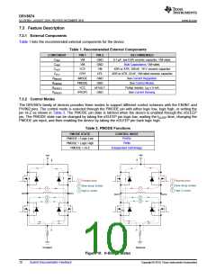
Table 6. IMODE Functions
IMODE FUNCTION
nFAULT
IMODE STATE
RIMODE = GND
Current Chopping
Mode
Overcurrent
Response
Response
Quad-Level 1
Quad-Level 2
Fixed Off-Time
Automatic Retry
Overcurrent Only
Current Chopping and
Overcurrent
RIMODE = 20 kΩ to GND
Cycle-By-Cycle
Automatic Retry
Current Chopping and
Overcurrent
Quad-Level 3
Quad-Level 4
RIMODE = 62 kΩ to GND
Cycle-By-Cycle
Fixed Off-Time
Outputs Latched Off
Outputs Latched Off
RIMODE = Hi-Z
Overcurrent Only
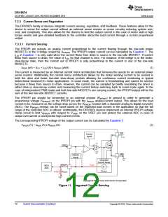
The current chopping threshold (ITRIP) is set through a combination of the VREF voltage (VVREF) and IPROPI
output resistor (RIPROPI). This is done by comparing the voltage drop across the external RIPROPI resistor to VVREF
with an internal comparator.
ITRIP (A) x AIPROPI (μA/A) = VVREF (V) / RIPROPI (Ω)
(3)
For example, if VVREF = 2.5 V, RIPROPI = 1500 Ω, and AIPROPI = 455 μA/A, then ITRIP will be approximately 3.66 A.
When the ITRIP threshold is exceeded, the outputs will enter a current chopping mode according to the IMODE
setting. The ITRIP comparator has both a blanking time (tBLK) and a deglitch time (tDEG). The internal blanking time
helps to prevent voltage and current transients during output switching from effecting the current regulation.
These transients may be caused by a capacitor inside the motor or on the connections to the motor terminals.
The internal deglitch time ensures that transient conditions do not prematurely trigger the current regulation. In
certain cases where the transient conditions are longer than the deglitch time, placing a 10-nF capacitor on the
IPROPI pin, close to the DRV887x, will help filter the transients on IPROPI output so current regulation does not
prematurely trigger. The capacitor value can be adjusted as needed, however large capacitor values may slow
down the response time of the current regulation circuitry.
The AERR parameter in the Electrical Characteristics table is the error associated with the AIPROPI gain. It
indicates the combined effect of offset error added to the IOUT current and gain error.
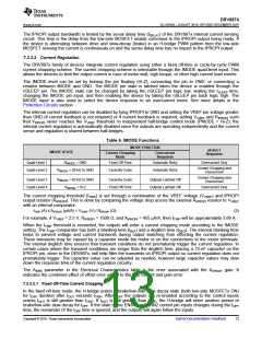
7.3.3.2.1 Fixed Off-Time Current Chopping
In the fixed off-time mode, the H-bridge enters a brake/low-side slow decay state (both low-side MOSFETs ON)
for tOFF duration after IOUT exceeds ITRIP. After tOFF the outputs are re-enabled according to the control inputs
unless IOUT is still greater than ITRIP. If IOUT is still greater than ITRIP, the H-bridge will enter another period of
brake/low-side slow decay for tOFF. If the state of the EN/IN1 or PH/IN2 control pin inputs changes during the tOFF
time, the remainder of the tOFF time is ignored, and the outputs will again follow the inputs.
Copyright © 2019, Texas Instruments Incorporated
Submit Documentation Feedback
13

 TI [ TEXAS INSTRUMENTS ]