DRV8874
SLVSF66A –AUGUST 2019–REVISED DECEMBER 2019
www.ti.com
7.3.3 Current Sense and Regulation
The DRV887x family of devices integrate current sensing, regulation, and feedback. These features allow for the
device to sense the output current without an external sense resistor or sense circuitry reducing system size,
cost, and complexity. This also allows for the devices to limit the output current in the case of motor stall or high
torque events and give detailed feedback to the controller about the load current through a current proportional
output.
7.3.3.1 Current Sensing
The IPROPI pin outputs an analog current proportional to the current flowing through the low-side power
MOSFETs in the H-bridge scaled by AIPROPI. The IPROPI output current can be calculated by Equation 1. The
ILSx in Equation 1 is only valid when the current flows from drain to source in the low-side MOSFET. If current
flows from source to drain, the value of ILSx for that channel is zero. For instance, if the bridge is in the brake,
slow-decay state, then the current out of IPROPI is only proportional to the current in one of the low-side
MOSFETs.
IPROPI (μA) = (ILS1 + ILS2) (A) x AIPROPI (μA/A)
(1)
The current is measured by an internal current mirror architecture that removes the needs for an external power
sense resistor. Additionally, the current mirror architecture allows for the motor winding current to be sensed in
both the drive and brake low-side slow-decay periods allowing for continuous current monitoring in typical
bidirectional brushed DC motor applications. In coast mode, the current is freewheeling and cannot be sensed
because it flows from source to drain. However, the current can be sampled by briefly reenabling the driver in
either drive or slow-decay modes and measuring the current before switching back to coast mode again. In the
case of independent PWM mode and both low-side MOSFETs are carrying current, the IPROPI output will be the
sum of the two low-side MOSFET currents.
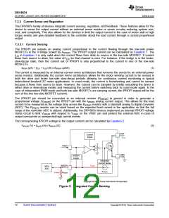
The IPROPI pin should be connected to an external resistor (RIPROPI) to ground in order to generate a
proportional voltage (VIPROPI) on the IPROPI pin with the IIPROPI analog current output. This allows for the load
current to be measured as the voltage drop across the RIPROPI resistor with a standard analog to digital converter
(ADC). The RIPROPI resistor can be sized based on the expected load current in the application so that the full
range of the controller ADC is utilized. Additionally, the DRV887x devices implement an internal IPROPI voltage
clamp circuit to limit VIPROPI with respect to VVREF on the VREF pin and protect the external ADC in case of
output overcurrent or unexpected high current events.
The corresponding IPROPI voltage to the output current can be calculated by Equation 2.
VIPROPI (V) = IPROPI (A) x RIPROPI (Ω)
(2)
OUT
ILOAD
Control
Inputs
VREF
+
LS
œ
GND
IPROPI
Clamp
Integrated
Current Sense
IPROPI
IPROPI
RIPROPI
MCU
ADC
+
VPROPI
AIPROPI
œ
Copyright © 2017, Texas Instruments Incorporated
Figure 11. Integrated Current Sensing
12
Submit Documentation Feedback
Copyright © 2019, Texas Instruments Incorporated

 TI [ TEXAS INSTRUMENTS ]