DRV8874
www.ti.com
SLVSF66A –AUGUST 2019–REVISED DECEMBER 2019
Control
Input
ITRIP
IOUT
Drive
Decay
Drive Chop Decay
Drive
VOUT
VIPROPI
nFAULT
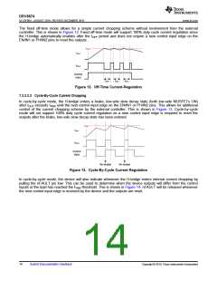
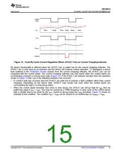
Figure 14. Cycle-By-Cycle Current Regulation Where nFAULT Acts as Current Chopping Indicator
No device functionality is affected when the nFAULT pin is pulled low for the current chopping indicator. The
nFAULT pin is only used as an indicator and the device will continue normal operation. To distinguish a device
fault (outlined in the Protection Circuits section) from the current chopping indicator, the nFAULT pin can be
compared with the control inputs. The current chopping indicator can only assert when the control inputs are
commanding a forward or reverse drive state (Figure 10). If the nFAULT pin behavior deviates from the operation
shown in Figure 14 then one of the following situations has occurred:
•
If a device fault has occurred, then the nFAULT pin pulls low to indicate a fault condition rather than current
chopping. Depending on the device fault, nFAULT may remain low even when the control inputs are
commanding the high-Z or slow-decay states.
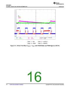
•
When the control inputs transition from drive to slow decay, the nFAULT pin will go high for tBLK then be
pulled low again if IOUT > ITRIP. This may be caused by a PWM frequency or duty cycle on the control inputs
with a off-time that is too short for the IOUT current to decay below the ITRIP threshold. Figure 15 shows an
example of this condition. The condition IOUT > ITRIP can be viewed on an oscilloscope as VIPROPI > VREF
.
Copyright © 2019, Texas Instruments Incorporated
Submit Documentation Feedback
15

 TI [ TEXAS INSTRUMENTS ]