DRV8874
www.ti.com
SLVSF66A –AUGUST 2019–REVISED DECEMBER 2019
The inputs can accept static or pulse-width modulated (PWM) voltage signals for either 100% or PWM drive
modes. The device input pins can be powered before VM is applied with no issues. By default, the EN/IN1 and
PH/IN2 pins have an internal pulldown resistor to ensure the outputs are Hi-Z if no inputs are present.
The sections below show the truth table for each control mode. Note that these tables do not take into account
the internal current regulation feature. Additionally, the DRV887x family of devices automatically handles the
dead-time generation when switching between the high-side and low-side MOSFET of a half-bridge.
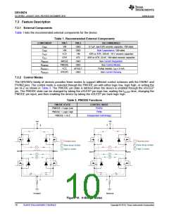
Figure 10 describes the naming and configuration for the various H-bridge states.
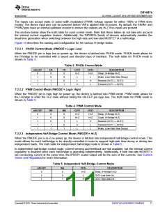
7.3.2.1 PH/EN Control Mode (PMODE = Logic Low)
When the PMODE pin is logic low on power up, the device is latched into PH/EN mode. PH/EN mode allows for
the H-bridge to be controlled with a speed and direction type of interface. The truth table for PH/EN mode is
shown in Table 3.
Table 3. PH/EN Control Mode
nSLEEP
EN
X
PH
X
OUT1
OUT2
DESCRIPTION
Sleep, (H-Bridge Hi-Z)
0
1
1
1
Hi-Z
L
Hi-Z
L
0
X
Brake, (Low-Side Slow Decay)
Reverse (OUT2 → OUT1)
Forward (OUT1 → OUT2)
1
0
L
H
1
1
H
L
7.3.2.2 PWM Control Mode (PMODE = Logic High)
When the PMODE pin is logic high on power up, the device is latched into PWM mode. PWM mode allows for
the H-bridge to enter the Hi-Z state without taking the nSLEEP pin logic low. The truth table for PWM mode is
shown in Table 4.
Table 4. PWM Control Mode
nSLEEP
IN1
X
IN2
X
OUT1
Hi-Z
Hi-Z
L
OUT2
Hi-Z
Hi-Z
H
DESCRIPTION
Sleep, (H-Bridge Hi-Z)
0
1
1
1
1
0
0
Coast, (H-Bridge Hi-Z)
0
1
Reverse (OUT2 → OUT1)
Forward (OUT1 → OUT2)
Brake, (Low-Side Slow Decay)
1
0
H
L
1
1
L
L
7.3.2.3 Independent Half-Bridge Control Mode (PMODE = Hi-Z)
When the PMODE pin is Hi-Z on power up, the device is latched into independent half-bridge control mode. This
mode allows for each half-bridge to be directly controlled in order to support high-side slow decay or driving two
independent loads. The truth table for independent half-bridge mode is shown in Table 5.
In independent half-bridge control mode, current sensing and feedback are still available, but the internal current
regulation is disabled since each half-bridge is operating independently. Additionally, if both low-side MOSFETs
are conducting current at the same time, the IPROPI scaled output will be the sum of the currents. See Current
Sense and Regulation for more information.
Table 5. Independent Half-Bridge Control Mode
nSLEEP
INx
X
OUTx
Hi-Z
L
DESCRIPTION
Sleep, (H-Bridge Hi-Z)
0
1
1
0
OUTx Low-Side On
OUTx High-Side On
1
H
Copyright © 2019, Texas Instruments Incorporated
Submit Documentation Feedback
11

 TI [ TEXAS INSTRUMENTS ]